
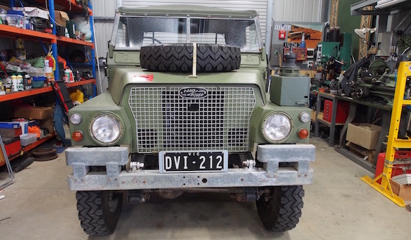
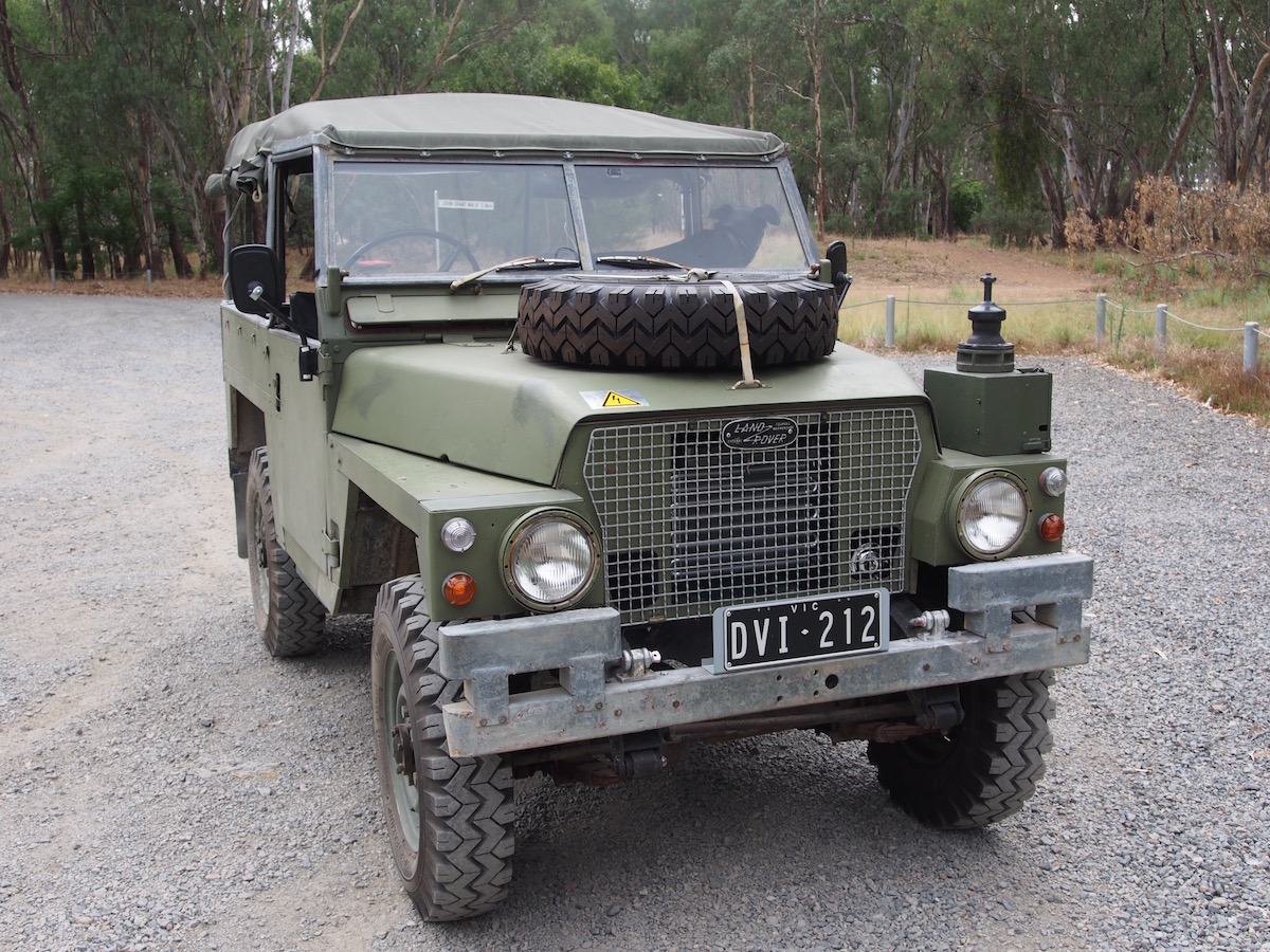
1973 Land Rover Series III, FFR Lightweight, EV conversion
2024 UPDATE : EV Landy now into its 7th year
EV Land Rover conversion has been 100% reliable & done well over 30,000km now, its a daily driver & fun 4x4
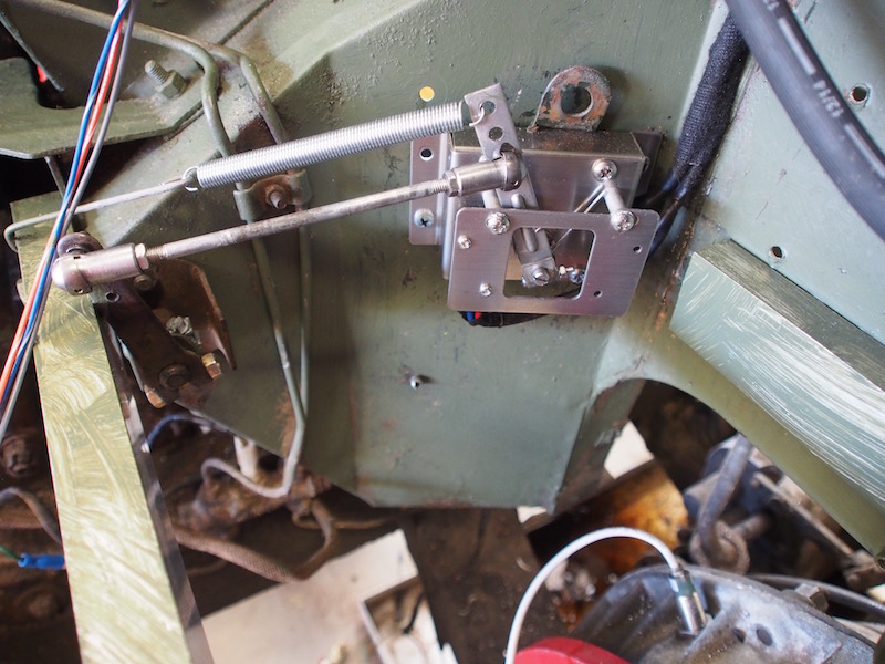
I've done a few upgrades over the time, it stopped well enough before but I used the vehicle as a test bed for my disc brake kit, and most recently I've added power steering, necessary due to a shoulder injury if I want to keep driving it on a daily basis.
Here is a video compilation of clips over that time.
DIY Electric Vehicle
I have been interested in building an Electric Vehicle for some time now and actually purchased a PT Cruiser with a blown engine for the purposes of converting but I could not find a VASS Engineer willing to sign off on a conversion where I needed to alter the crumple zone so after thinking long and hard I took a giant leap of faith and pulled the perfectly good 2.25L internal combustion engine from my ultra rare (in this country) 1973 Land Rover Lightweight.
Since there were no crumple zone ADR's (or Air Bags) in 1973 I dont have to worry about them.
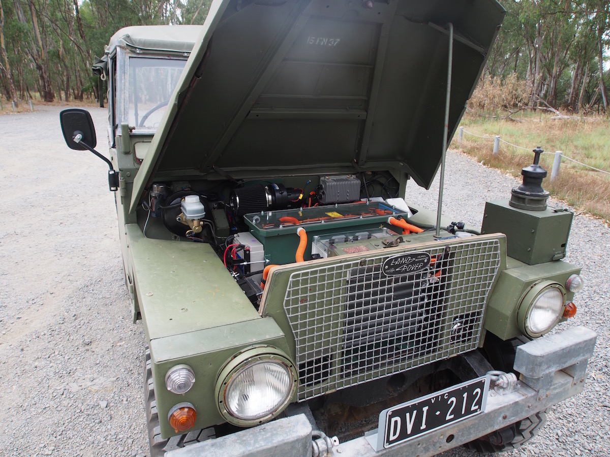
The Land Rover has no Aircon, no Power Steering, no Power Seats, no Power Windows, no ABS, no Airbags, no CANbus, no ECU, that's win win win win win in favour of converting the Land Rover, and the two under-seat fuel tanks are perfect locations to mount LiFePo4 cells, more must be mounted under the bonnet over the new Electric Motor to maintain the original weight distribution.
First test drives 15 Jan 2018
The Build
I needed to be mindful that I am working with a very rare (esp. in this country) classic vehicle & I will be drilling no un-necessary holes or altering the bodywork or chassis to accommodate the EV conversion, and there will be no visible external difference to original apart from lack of an exhaust tail-pipe.
The conversion will save me fixing the leaky Zenith Carby (again) and will be completely reversible and I can reconfigure to original (if it does not work out).
August 2017,
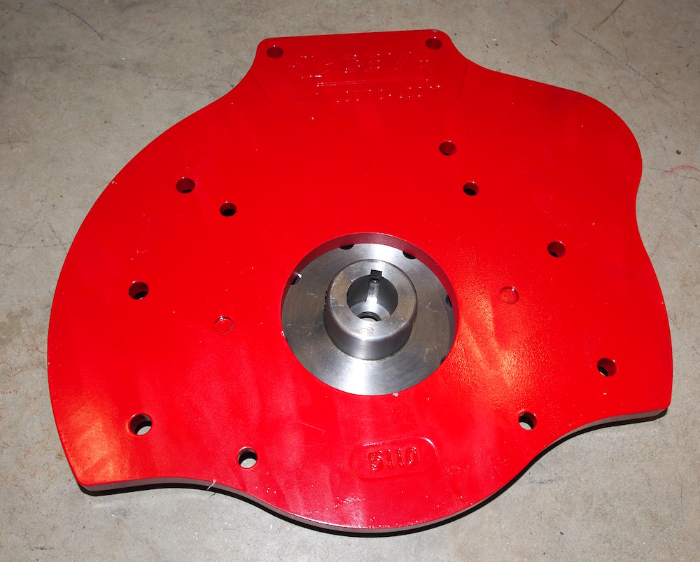
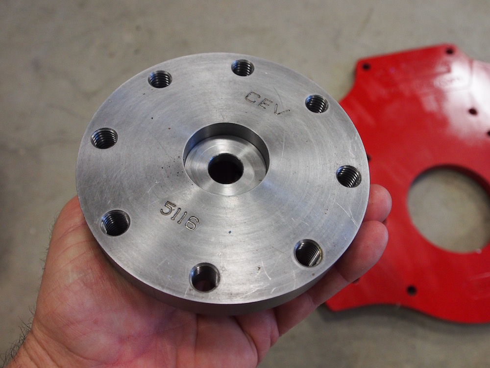
Being my first EV conversion I did a bit of internet research and found a bloke in Colorado had converted a Series 3 to EV . He used a DC Kostov motor bolted to the existing gearbox using an adaptor plate from Canadian Electric Vehicles. so I followed his lead and placed an order with Randy from Canev. It would have been possible to bolt a motor direct to the transfer case but I wanted to keep the vehicle as original & complete as possible. That includes keeping the gear stick & clutch pedal.
Gearbox Adaptor & flywheel hub kit arrive one week later .

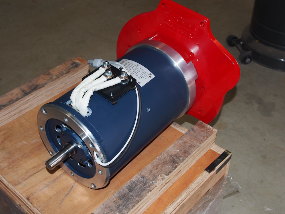
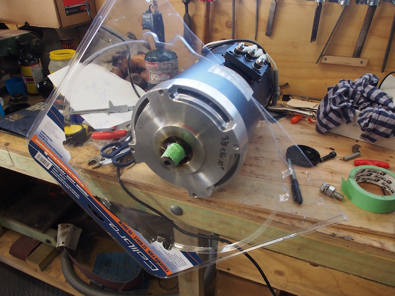
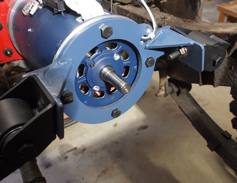
Meanwhile I ordered my motor, ( 3 Phase AC ) HPEVS AC51 & Curtis 1239E Controller from EV Works in Western Australia which had to come from California. The reason I chose an AC motor over a potentially cheaper more powerful DC Motor was because I wanted regenerative braking for this project. (Regen is possible with some DC motors but is complicated & commutator lifespan is very short) Regen Braking means the Motor acts as a generator and provides braking power by converting kinetic energy into electricity, thus charging the batteries, it also recharges the batteries down hill & can be adjusted with a 5K pot, (I'm hoping to experiment there & use it for hill descent control in Low Range)
Motor arrived on 26 Sept, As soon as I unpacked the crate I made sure the CanEV Rover adaptor bolted up. Now I had enough parts for the project to go ahead so pulled the perfectly good Land Rover ICE out (Internal Combustion Engine) on 13 October.
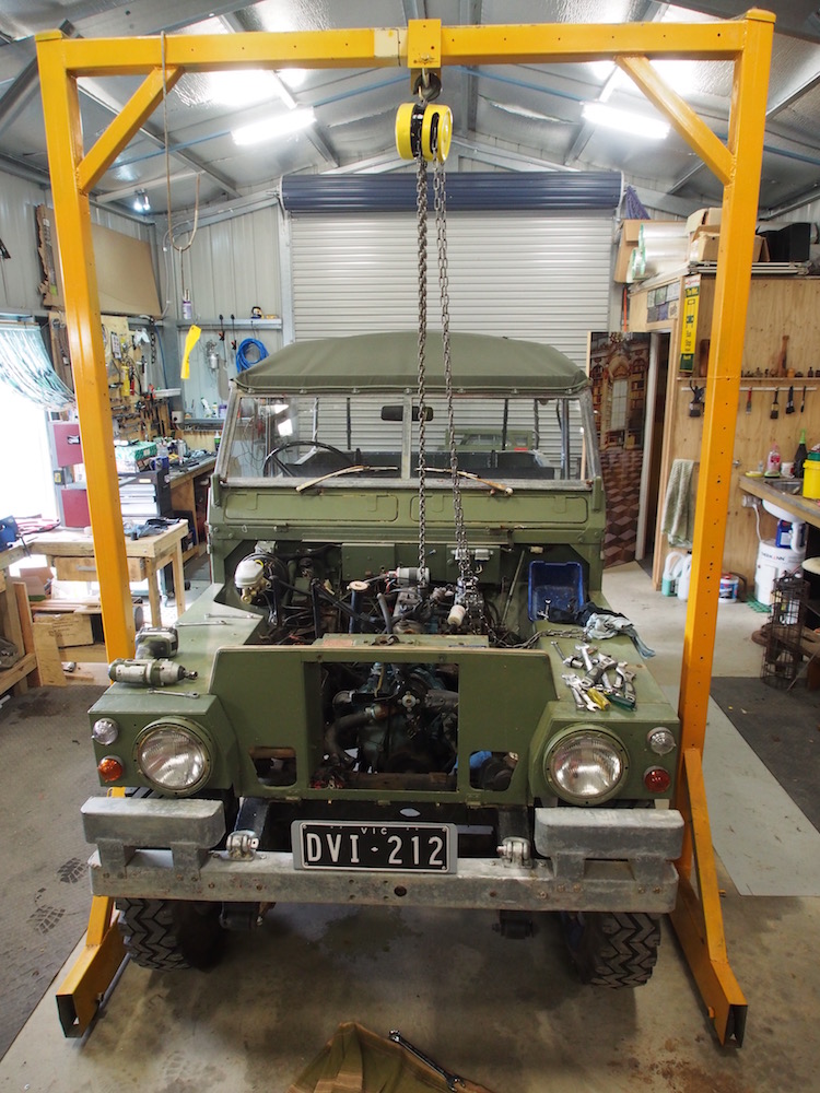
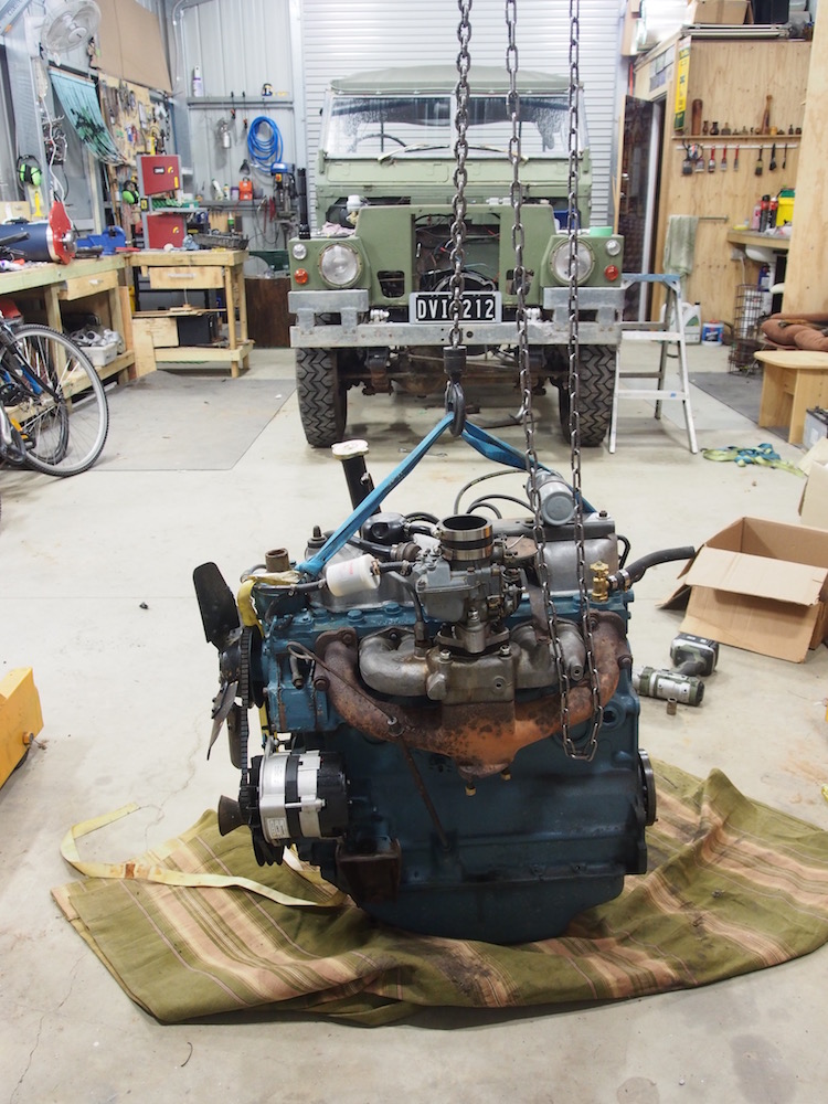
As well as the Engine (250kg) I removed all the other parts that wont be needed, Including Radiator, Air Filter & mounting bracket including ZZ70 Lead Acid starting battery, Exhaust System and Fuel Tanks. Easily another 50Kg.
The new motor and adaptor is about 60kg, and 260kg of batteries so tare weight is about the same, but in reality a lot less because 2 x full fuel tanks weigh about 40kg each and they are displaced by part of the battery load.
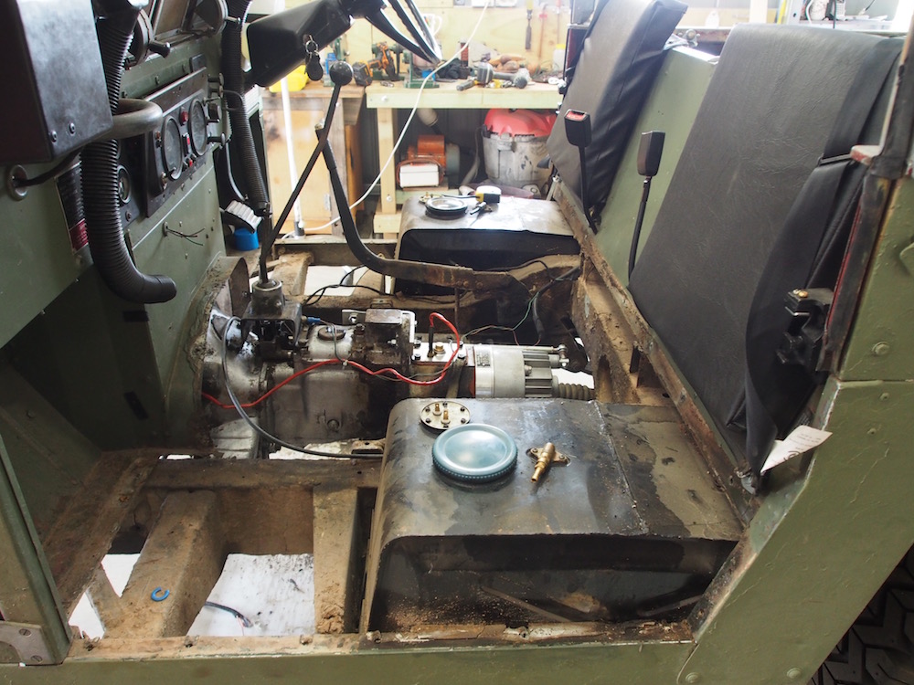
The fuel tanks are dropped from underneath but I also removed the floor panels and seat box to give me better access for cabling at a later stage. Note that the petrol fill caps are on top of the tanks. There are no external fuel caps on a Lightweight, filling with petrol involves lifting the seat cushion, then removing an aluminium cover, followed by the cap. No matter how careful you are the interior stinks of petrol, which remains usually until both tanks are half full & stop sloshing around the breathers in the bottom of the caps. That's a good reason to convert to EV in itself.
Downside of having no external filler is there is no obvious place to install a J1772 charging socket !!
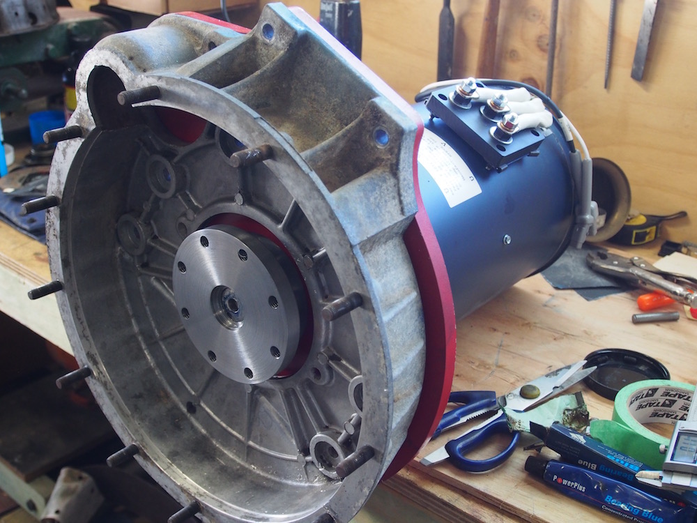
Fitting up Motor to Gearbox
I noted whilst reading about the Land Rover conversion on adventure-ev.com that Jeff G. found the flywheel was not in the correct plane when fitting his Kostov DC Motor to the CanEV adaptor, The adaptor was designed for a Netgain Warp9, Jeff had to make a .75" thick spacer to move the motor forward bringing the flywheel into the correct plane. Being mindful of this I took some measurements and found with the AC51 I had a similar issue but dealt with it in a different way.
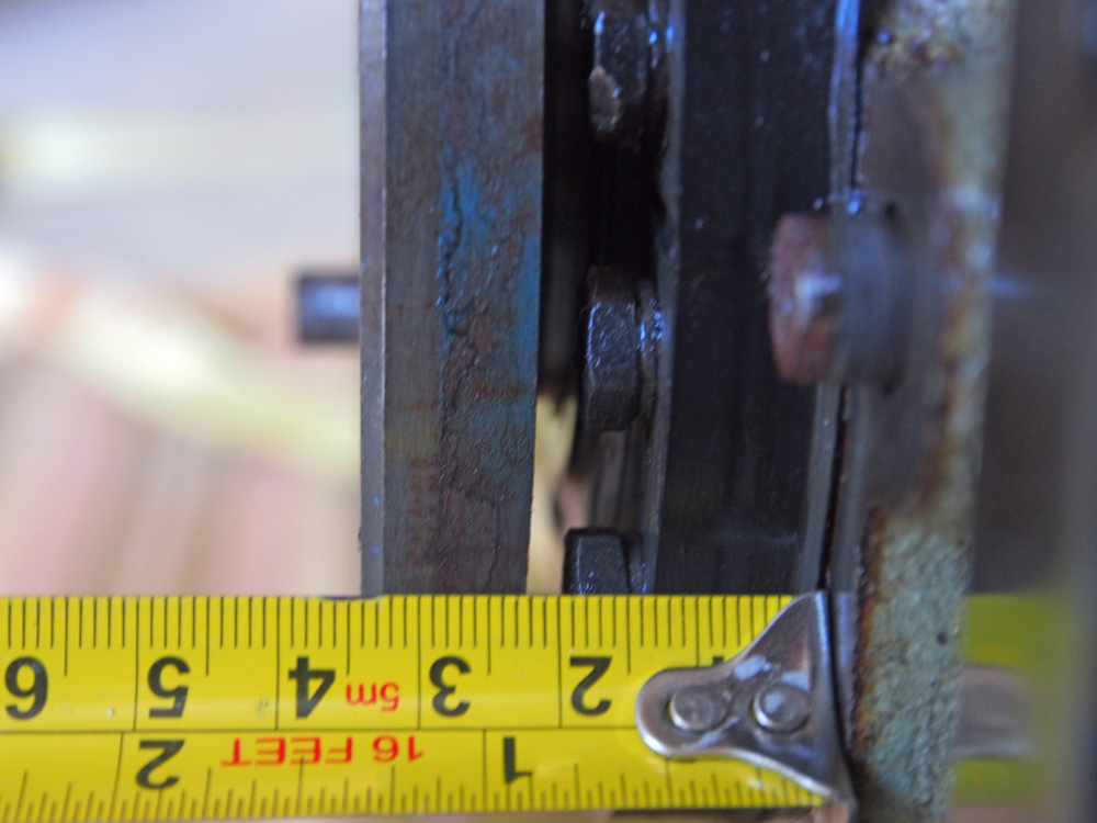
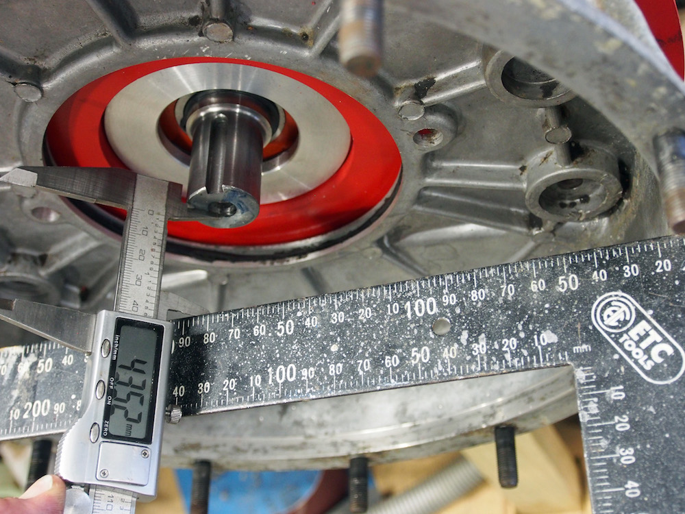
Original crank flange is 34mm from back of engine, as seen in image to the left.
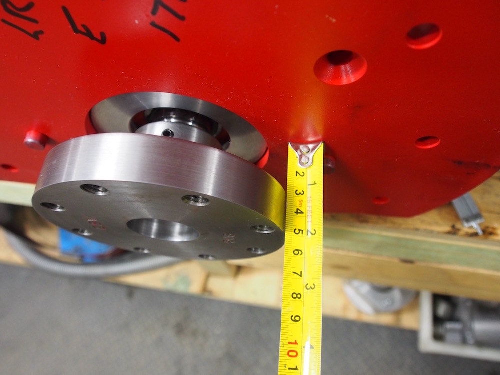
New motor and adaptor the same relationship is 51mm, To fix the issue the motor needs to be spaced 17mm forwards, or the rear face of the adaptor hub needs to be moved forward 17mm
The adaptor hub is much thicker than the crank flange, so there is about 11mm of material I can remove.
The recess for flywheel protusion now needs to be deeper, so was adjusted accordingly
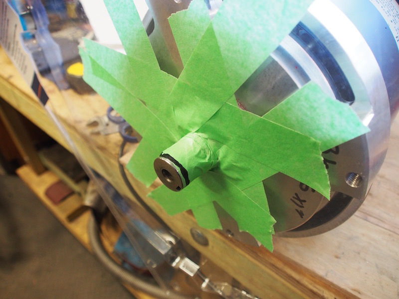
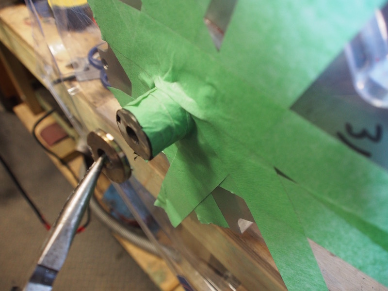
The hub now need to be moved a further 6mm forward, I trimmed 4mm from rear of motor shaft, being careful to protect it to avoid ingress of sparks, If you plan on doing the same conversion I recommend you order your HPEVS motor with a shorter shaft to avoid this surgery.
This leaves 2mm which can be taken up with clutch adjustment.
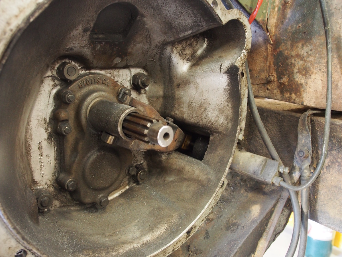
Now there is a new problem. Measuring from the bell housing mounting plane to the rear of the motor shaft is 43.25mm, Measuring from the bell housing plane to the gearbox input shaft = 46mm so I have to lose 3mm from the input shaft. In retrospect spacing the motor forward might have been a smart solution. Too bad there are no instructions - oh, I guess I'm writing them 🤣 🤣 🤣
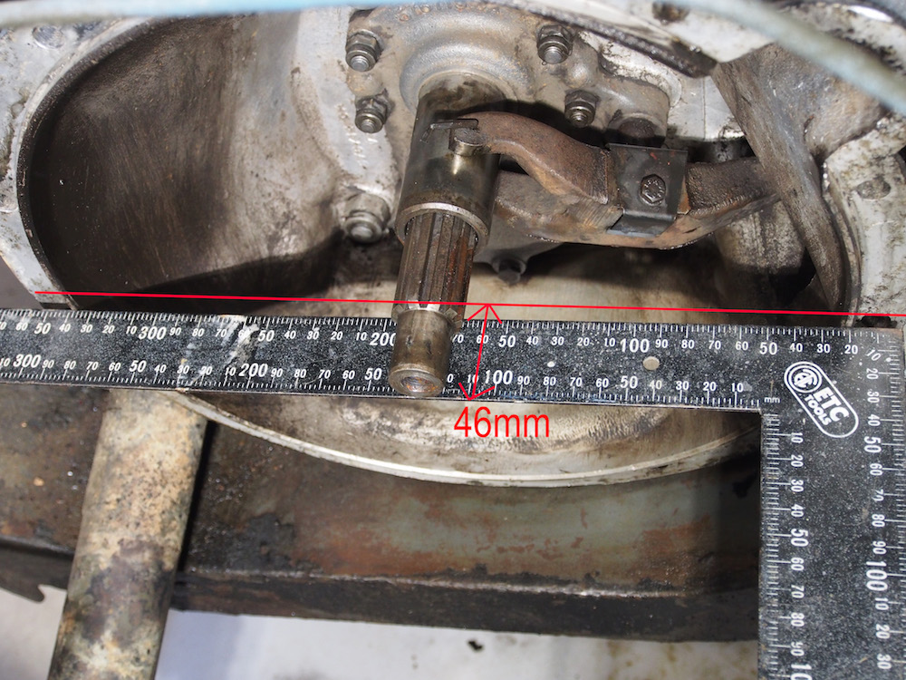
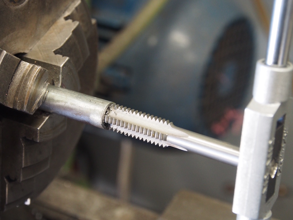
Removing the chamfer from the input shaft was all that's needed, This will only be a problem when lining the gearbox up to motor if the clutch is not correctly cantered.
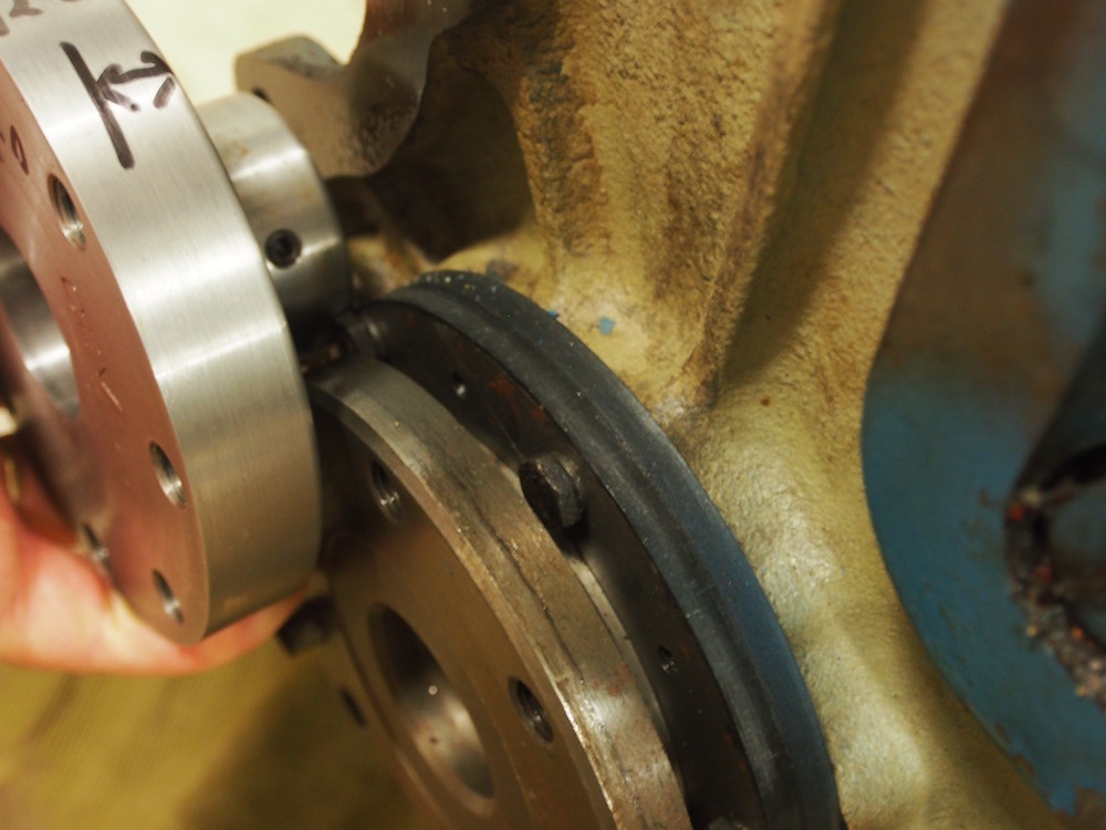
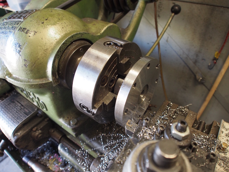
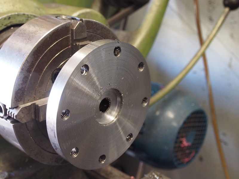
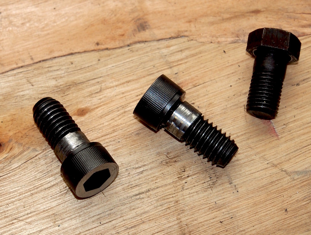
To prepare the flywheel I removed the ring gear by tapping with a hammer and suitable drift and cleaned it up on the lathe. Upon fitting of the flywheel to motor I found the CanEV adaptor used UNC bolts but the Rover Flywheel bolts are UNF, I could find no Grade 12 UNC bolts with a stepped shank (needed to centralise the flywheel) so had to make some sleeves by drilling & tapping some mild steel rod. These were fitted to Unbrako cap head bolts with retaining compound. (center photo below shows 2 new bolts plus on original rover bolt). I also skimmed the top off the bolt heads as they may come into contact with the clutch springs as the friction material wears (probably never)
IMPORTANT UPDATE
Randy from CanEV has contacted me and advised they are retooling the Land Rover Series adaptor kit, The plate will have 17mm spacer built onto it and the Hub adaptor will have the correct UNF 7/16 threads to accept original Rover flywheel bolts. None of the above faffing about will be required. Thats what I call proactive after sales service
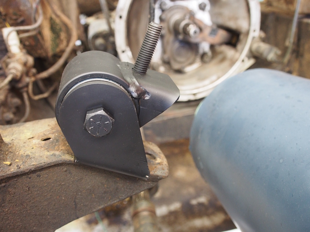
Motor mount
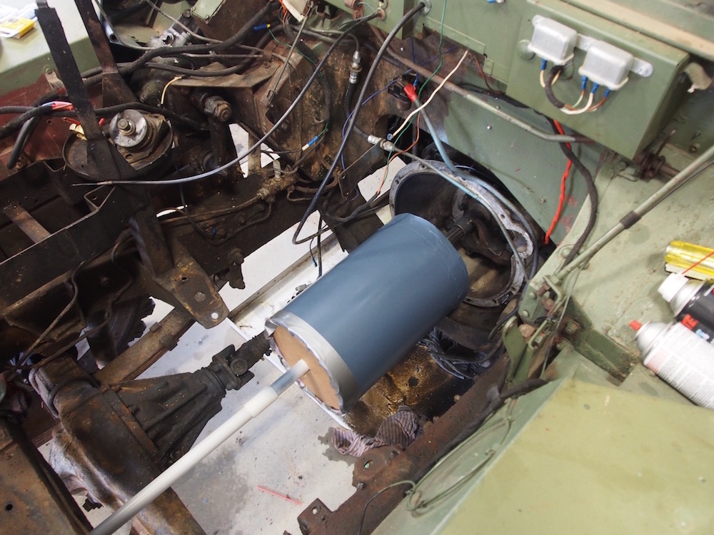
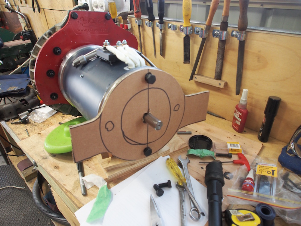
Now that the Motor is all good to bolt up to the Gearbox its time to design a front motor mount. I made a "dummy" motor from a short section of sewer pipe, same diameter and length as motor . The Land Rover has a hole in the front cross member where one could use a crank handle to start the engine in the event of a flat battery. ( I cant think of any other vehicle made in 1973 that has this feature - In Fact Land Rover Series 3 used it up until end of production in 1984!! ) I placed a curtain rod through the centre of dummy motor, onto gearbox input shaft and through crank handle hole to get a perfect alignment for working out my motor mount.
McBurnie's the local engineering supply prefer DXF file to the cardboard cutouts I generally use so I downloaded QCAD, a free 2D CAD program that will save in DXF format, it took a couple of days to learn but I finally managed to produce a dxf drawing and had my mount cut from 10mm plate, gussets are 6mm
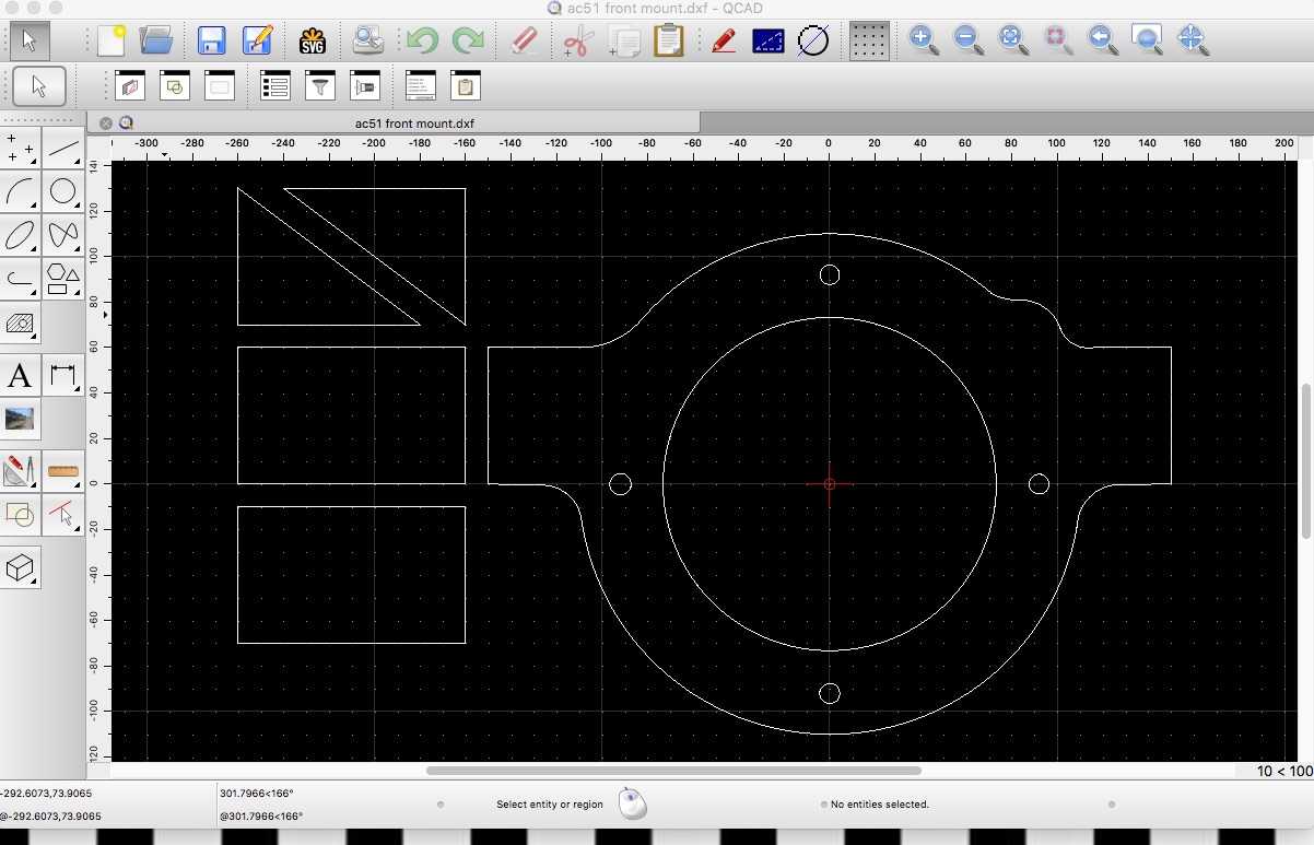
I found some Unbreakable LS1 rubbers on eBay from Mace engineering, these are perfect because they can fully articulate and made the design much easier than it would have been using Land Rover rubbers
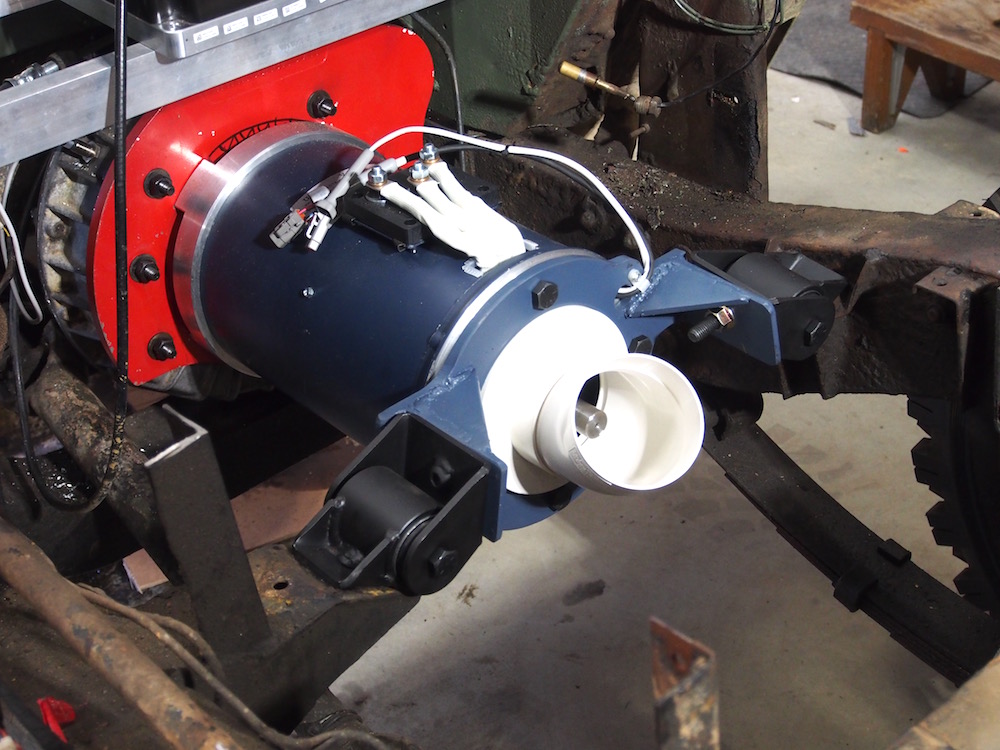
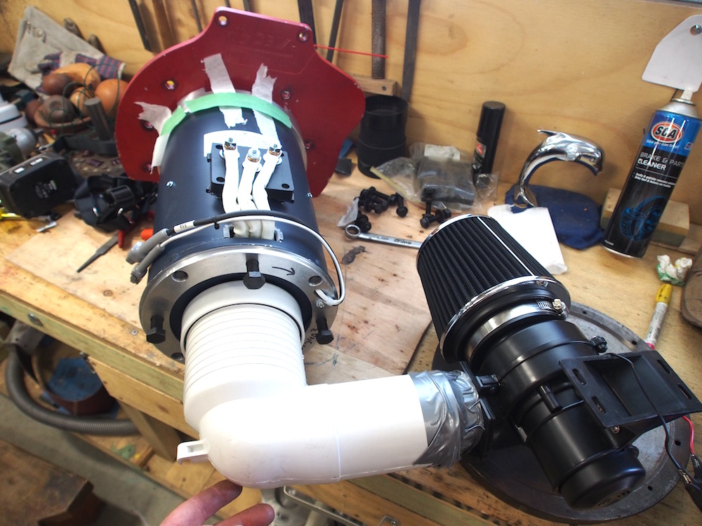
The AC51 has an internal fan to draw cooling air through from the front to the rear, Not ideal on a 4x4 to ingest dust, mud, water and road spray so I cobbled together some ducting to supply clean air via a Pod filter and 12v Marine blower, the image below shows bench testing.
These motors can be supplied as oil cooled in which case they are fully sealed.
Batteries
Batteries are the most expensive part of the conversion & have to be considered carefully. It is a no brainer to choose Lithium over Lead Acid , even though they are more expensive, Lithium have an 80% depth of discharge compared to 50% (at best) for lead and have about 10x the amount of charge cycles for about 1/3 of the weight.
Unfortunately there is no supply of salvaged Nissan Leaf / Chevy Volt or Tesla cells in Australia. (at the time of writing in 2017 ) This being my first EV project I decided Prismatic cells would be the most straightforward option. I was originally thinking about CALB180 LiFePo4 3.2volt cells, My motor requires 144v nominal, which means 45 cells.
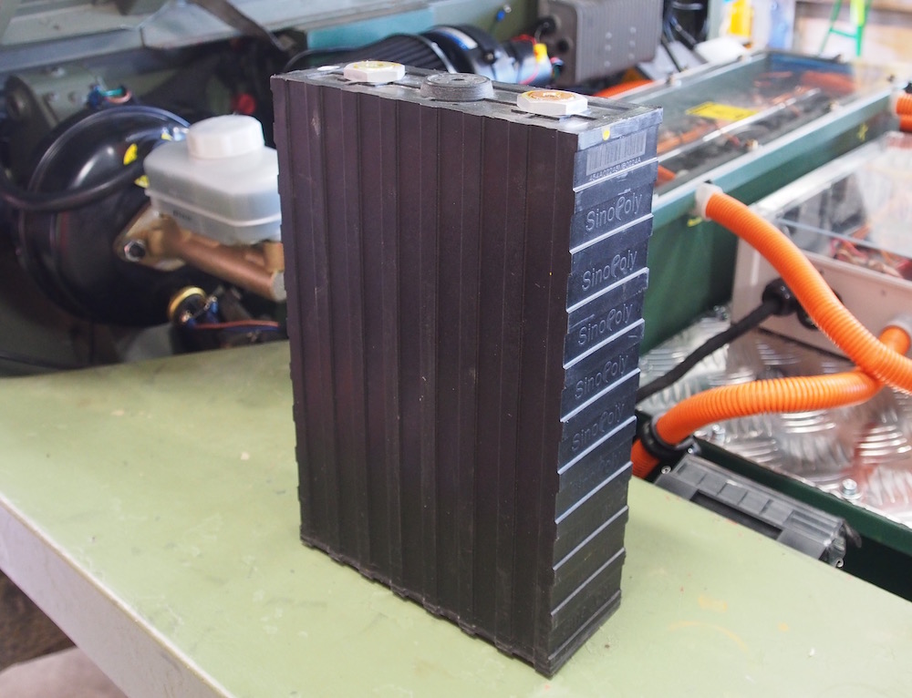
Ultimately I got a great deal on SinoPoly 200Ah LiFePo4 (Lithium, Iron, Phosphate) cells from Neale at Milbay Australia. The Sinopoly cells are the same size (280 x 180 x 70mm) and weight as CALB180, but are rated at 200Ah. At 5.8kg each the entire 144Volt pack weighs in at only 261kg (200Ah in Deep Cycle Lead acid would weigh 710Kg ). Therefore the Lithium batteries plus 60kg motor weigh less than the petrol engine and fuel tanks they are replacing
I should point out that LiFePo4 Cells are very safe, They contain no corrosive acid, and no explosive gases. "Lithium" batteries have a bad reputation for exploding or catching fire but dont get confused, Its Lithium Polymer as used in R/C Models, Phones & Hoverboards that created that perception. Lithium Iron Phosphate are completely safe, actually a million magnitudes safer than the petrol they are replacing.
Below is a video made at the SinoPoly factory.
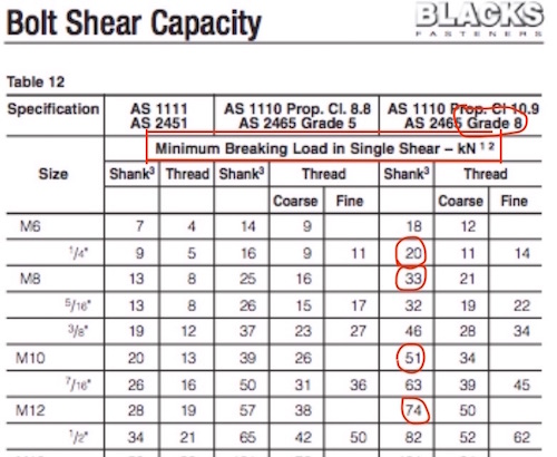
Whilst waiting for batteries to arrive from Milbay, which only took a couple of weeks to, first from China, then 2 days from Gold Coast. I designed the battery boxes. Australian regulation NCOP-14 require the battery enclosure to be able to sustain 20G frontal Impact, 15G side and 10G Rear & Inverted. This means I need to mount one 70Kg battery box so that its fixings can handle 1400kg. Fair enough don't want batteries becoming potential missiles. Those figuires seem unatainable but when you consider the Land Rover chassis is made from only 2mm thick steel its pointless making the boxes from 6mm plate steel. When you consider a 8.8 1/4" UNF bolt has a shear strength of 20kn = 2000kg force
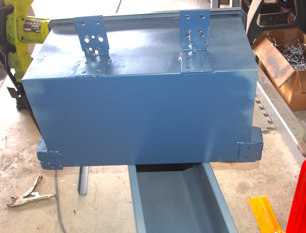
I had my Boxes professionally made from 1.5mm steel so that they comply with the relevant engineering standards.
For a battery box containing 12 cells = 70kg x20g = 1400kg the equivalent of one 1/4" bolt is sufficient, so I'm confident the fixing of my battery boxes are over engineered as I'm obviously using more than one bolt. I hope my VicRoads VASS Engineer sees it the same way. (VASS = Vehicle Assessment Signatory Scheme)
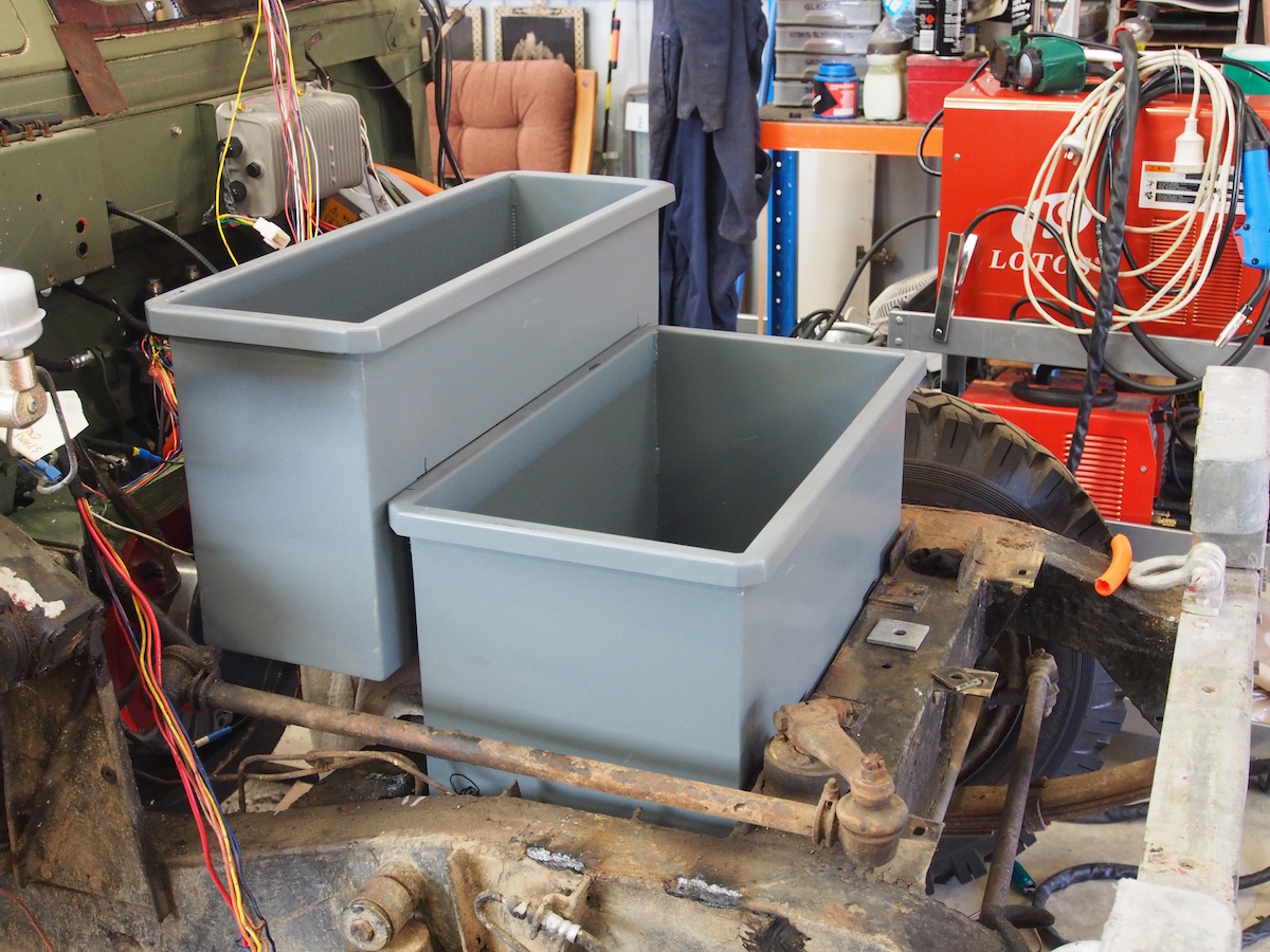
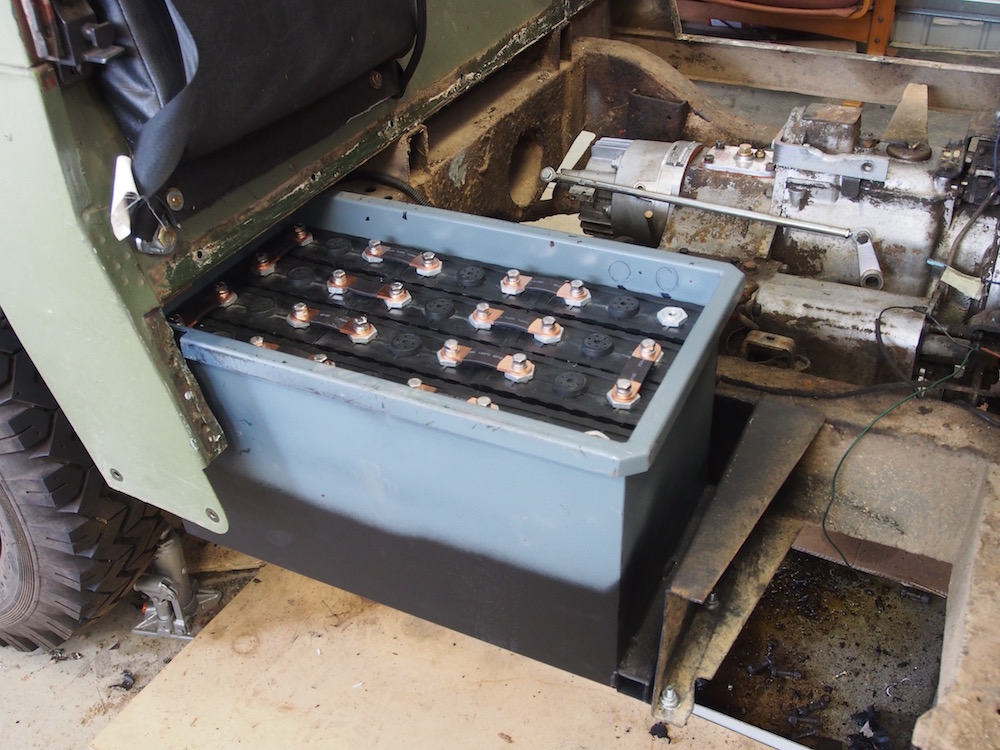
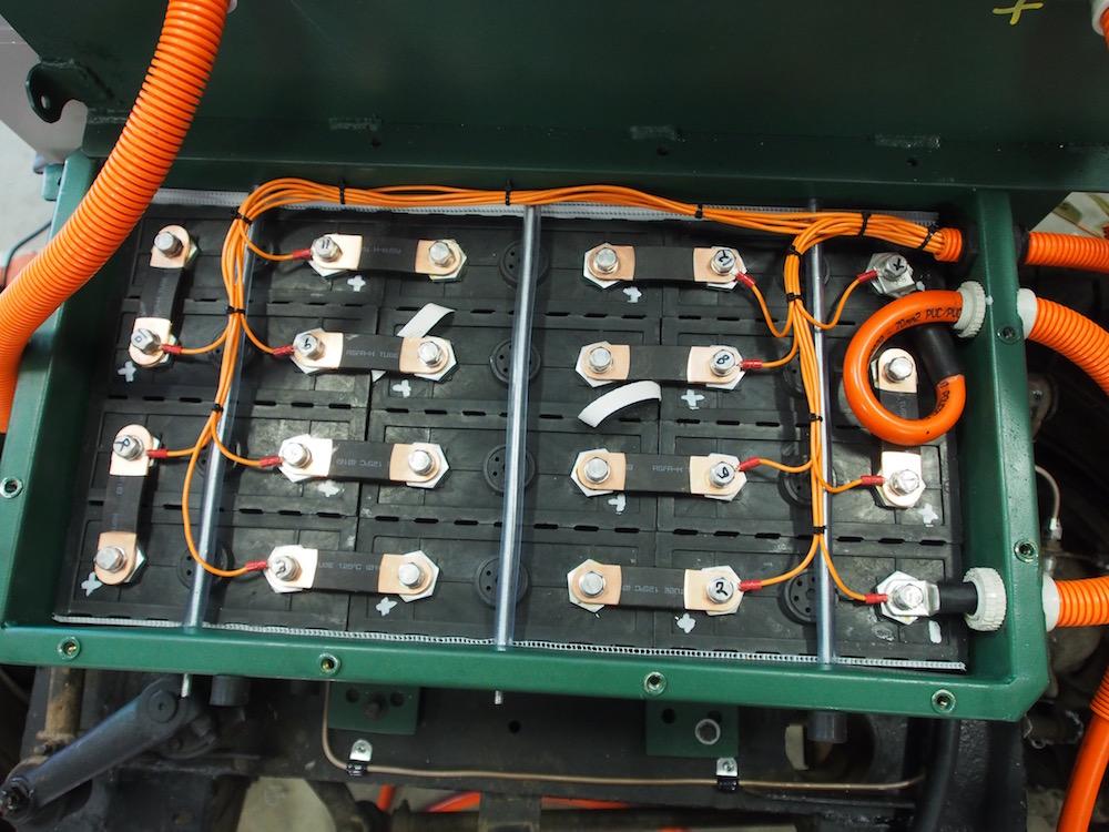
Luckily when arranging 12 x SinoPoly LFP 200AHA Cells in a 4x3 configuration the external dimensions are almost the same as a standard Lightweight 45 Liter fuel tank so I dimensioned the boxes accordingly with room for coreflute insulation on the bottom and sides. And a lip at the top to add strength and allow fixing for perspex or alloy lids.
The cells need to be packed at tight as possible and then clamped in place.
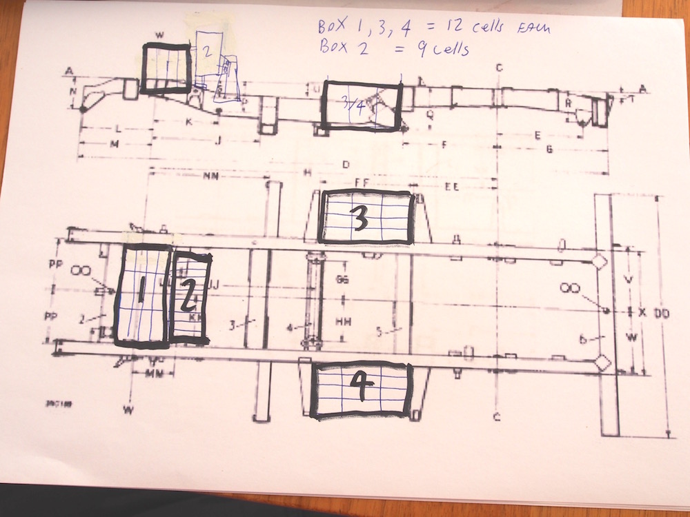
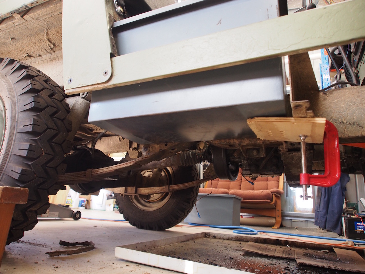
Since I am using 45 x cells I divided the layout into 12 for each original fuel tank position, another fuel tank sized box of 12 where the radiator used to be (between the chassis rails and behind front cross member) and a box of 9 behind that which is elevated to give clearance above motor.
The SWB Land Rover fuel tanks are in the perfect place to retrofit with batteries, as being between the wheels, weight distribution is not adversely affected, if at all, therefore no need for suspension or brake modifications.
For the Battery Boxes in the fuel tank location I copied the fuel tank mounting arrangement, but instead of 1/4" bolts I have used 6 x Grade M8 bolts on each tank. The combined shear strength of the 6 bolts are 19,800 kg , sufficient to withstand 20G impact (1,400kg) !! The original petrol tanks have only one bolt at the rear , but obviously I am using three . The angle brackets are 3mm steel, migwelded to the battery boxes.
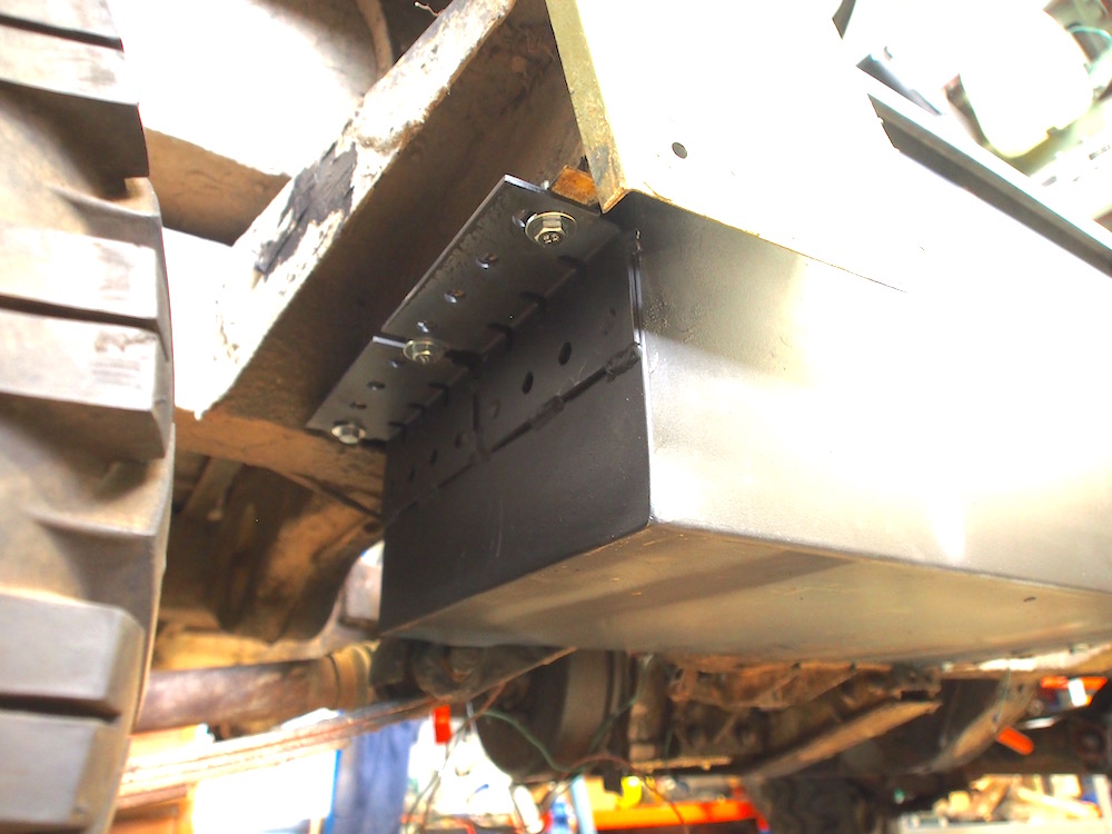
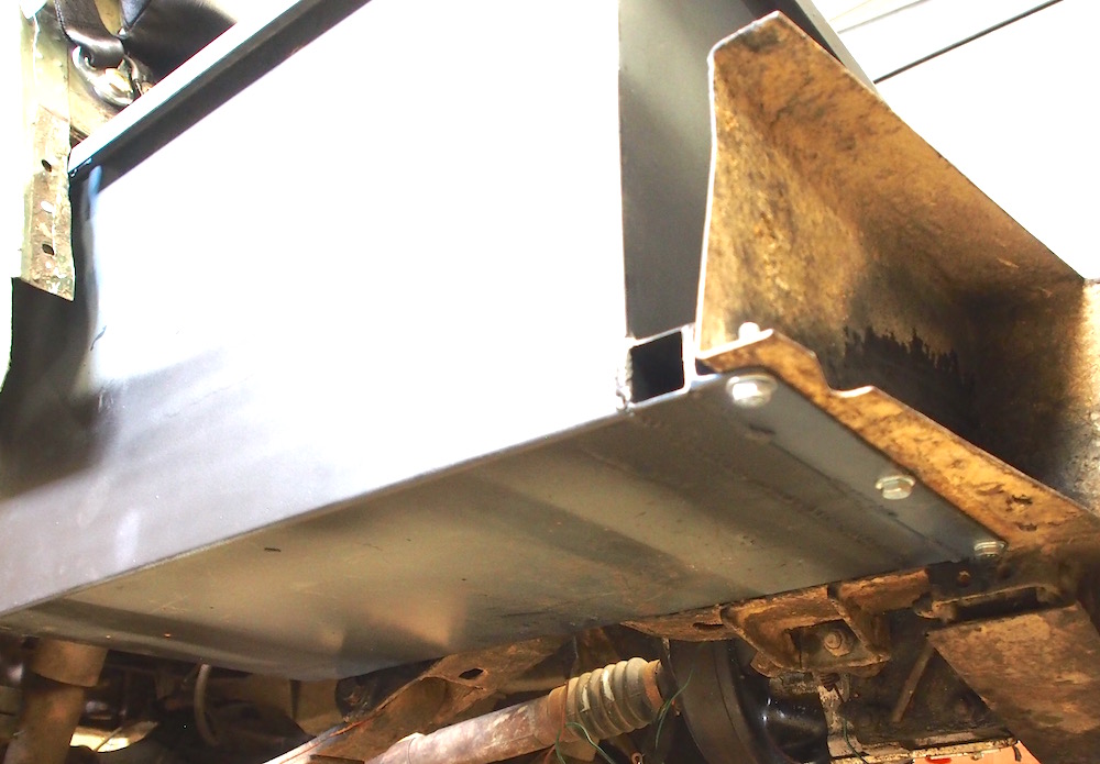
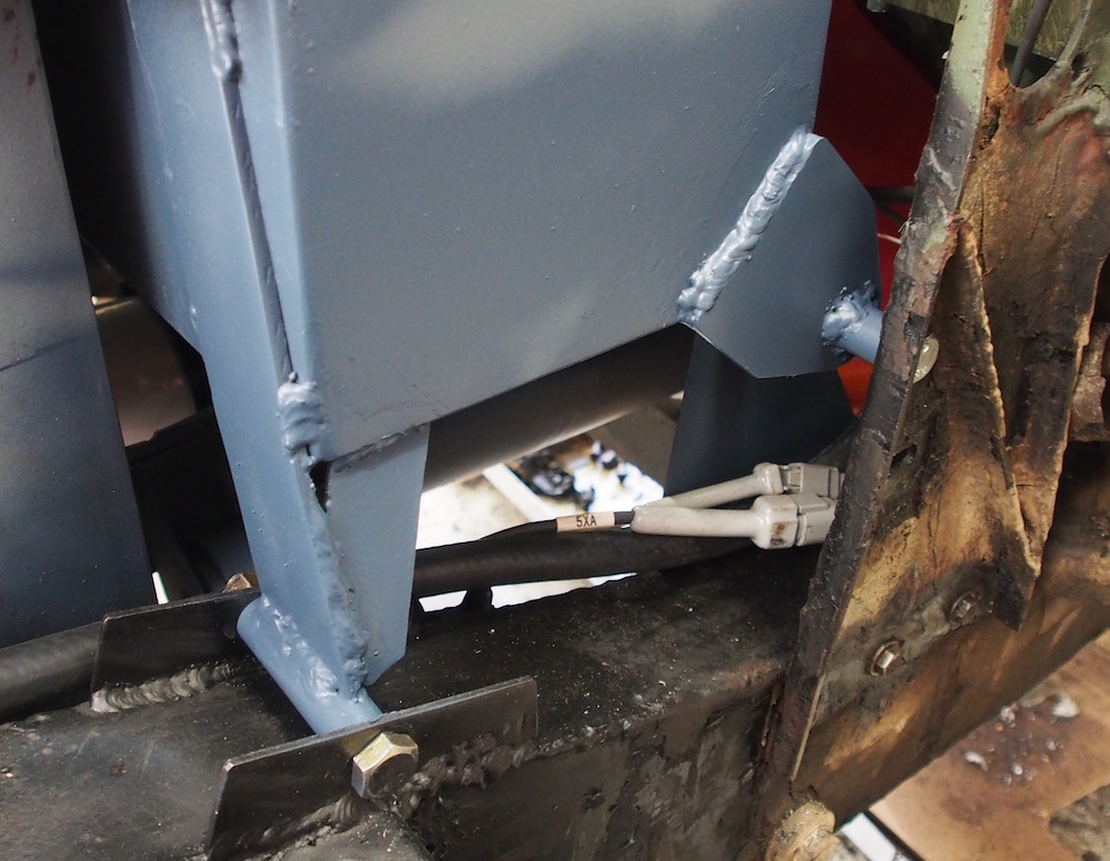
The front battery box is probably the most protected , and maybe it needs to be . its surrounded by chassis on the front and both sides. Is sits down into the chassis as far as possible (about 12mm) to still allow diff clearance when on fully compressed suspension bump stop. The front mounting brackets fix to the top of the chassis cross member using 4 x 1/4 Grade 8 bolts into the 8mm thick oil cooler support tabs. The Rear of the front box has 3mm brackets fixed by the 1/2" shock absorber top bolts.
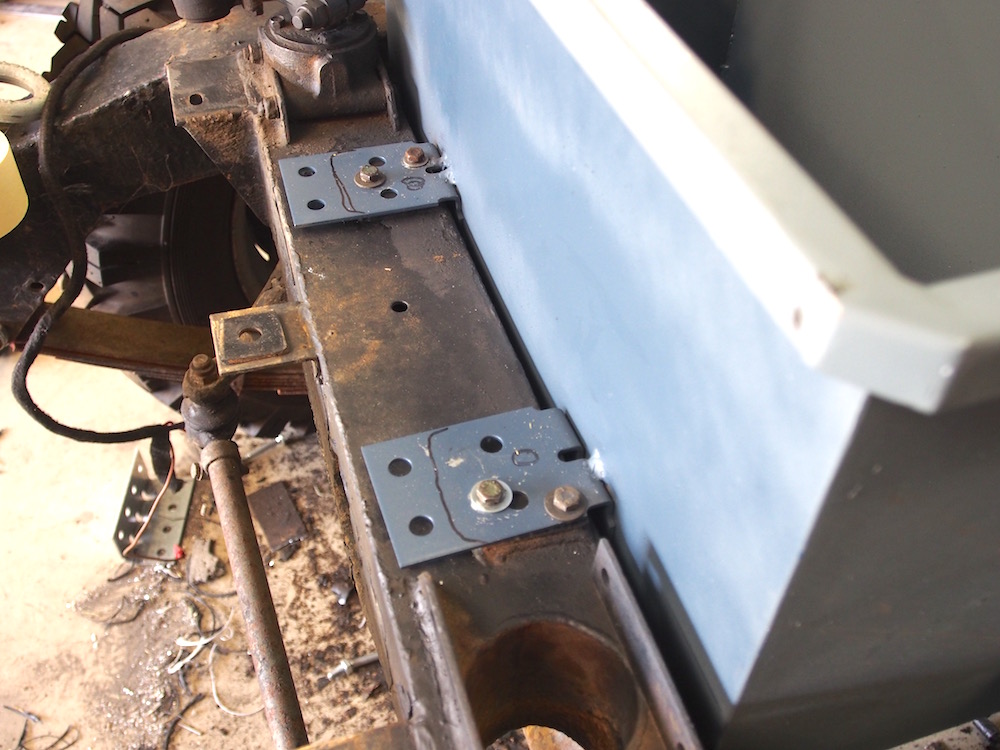
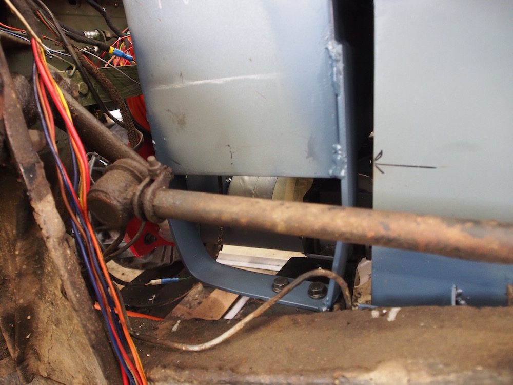
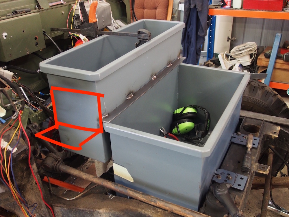
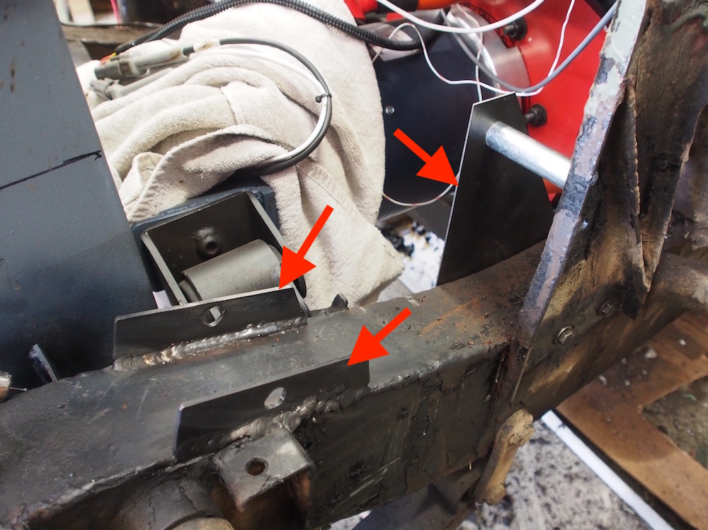
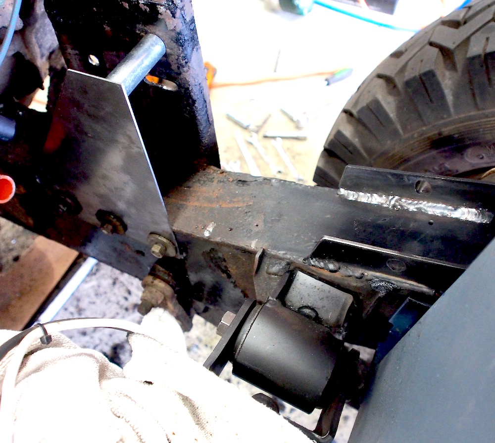
Mounting the 9 cell box is not so straight forward, sitting above the motor there are no obvious mounting points, I welded an angle iron along the front so that it sits along the rear edge of front box. Having the boxes tied together to share the mounts of each makes them both stronger. For the offside I made a mount from 6mm strap that attaches to the original engine mount strut using 2 x Grade 12 M10 bolts. Special consideration was given to allow for an unobstructed steering drag link and ball joint.
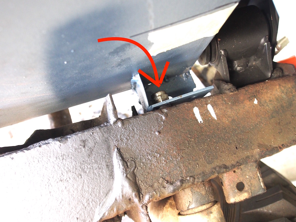
The red L shaped marking indicates where I'll be mounting my small Aux 12V battery, Hazard lights need to be operable for 20m with a disabled traction battery ie. DC-DC Converter not functioning.
To mount the 9 cell box I added a crush tube mount to the top of the nearside chassis rail. This is the only mod I needed to do to the chassis apart from cutting off a non standard battery mount bracket a previous owner had done, being an FFR (Fitted For Radio) this vehicle originally had its 24v battery between the seats. I also added a bracket to the inside of chassis using the bulkhead support bolts, a crush tube is fitted between the new bracket and firewall support plate.
M12 Grade 8 bolts used here, 7400kg shear strength, more than adequate for the job.
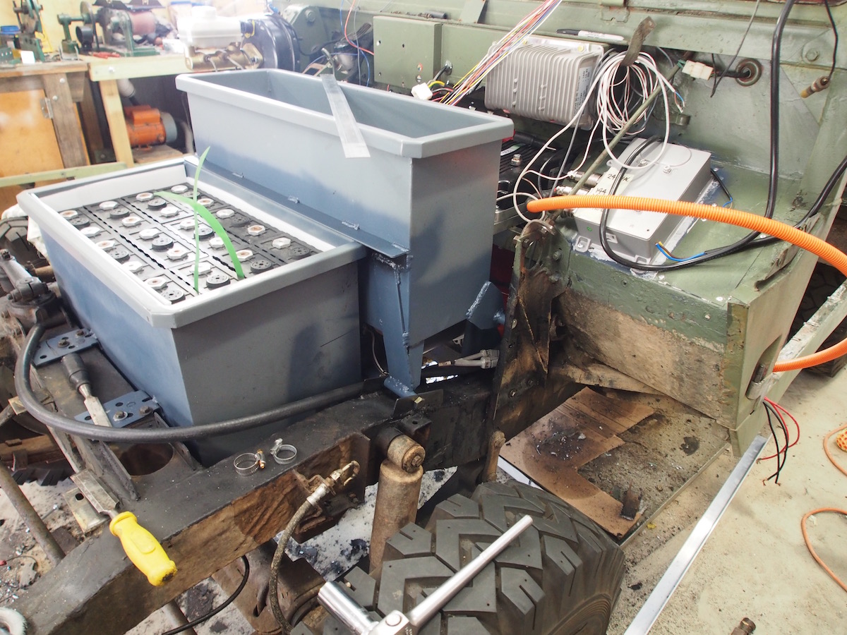
Battery Boxes done!! Test fitting 12x cells up front. You might wonder,... why the chisels? The chassis, underside of bodywork and inner guards have been covered in a thick layer of bituminous goop, Its great at preserving the chassis, there is no rust whatsoever, but it looks like crap. If I need to clear a section of chassis I heat the goop up with propane torch & scrape off, revealing a chassis that looks like the day it rolled out of the factory 45 years ago.
The banding strap around one cell is to help lift it out, not advisable to lift using battery lugs.
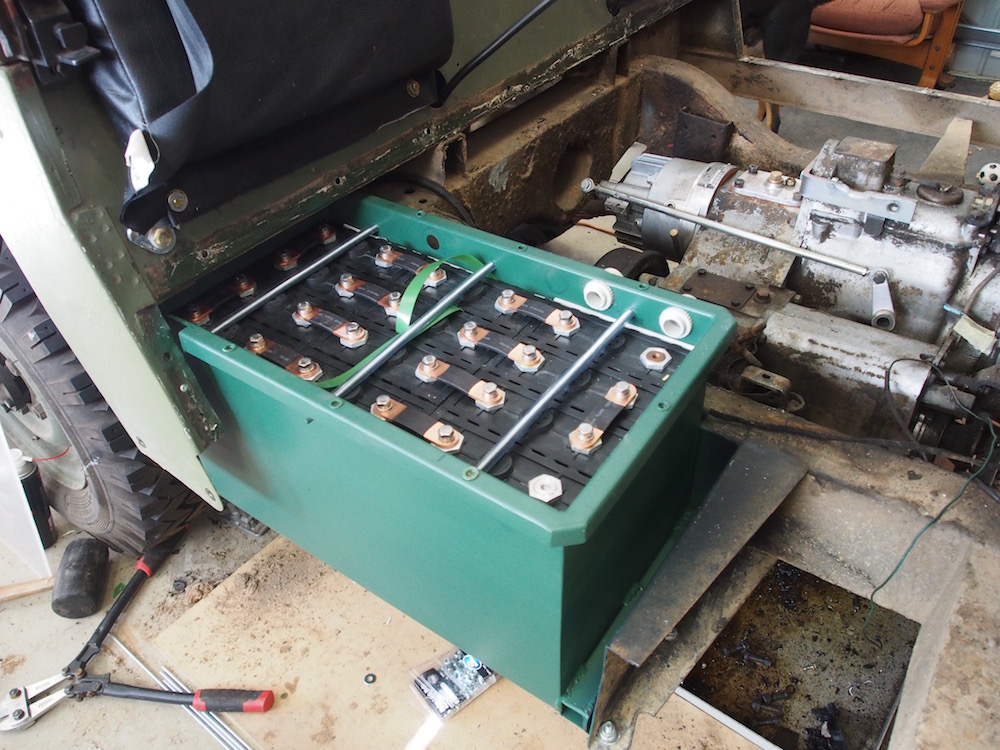
The method I use to secure the cells into the boxes is to fit them as tightly as possible by packing the outside edge with coreflute then use lengths of threaded rod, (insulated with clear vinyl tubing ) Tightening the rods squeezes the outsides of the boxes together thus clamping the cells together. The rods across the top of the tightly packed cells also prevents movement. This serves two purposes, one to keep the cells from swelling when charging and also to satisfy NCOP14 regarding cell containment.
I have also installed M6 Nutserts into the box top flanges to secure perspex covers.
That's enough on battery boxes, will get to wiring them up later
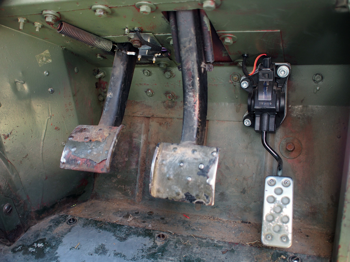
Brakes
The Lightweight brakes are dual circuit with a vacuum servo (booster) and a shuttle valve to warn of hydraulic failure in one of the lines. The key word being "Vacuum". The brake servo gets its vacuum supply from the inlet manifold of the original petrol engine, but there is no inlet manifold on an electric motor so we have to come up with another vacuum source.
One solution is to use a vacuum pump from a turbocharged car, because of its forced induction ( Boost pressure) there is no vacuum on an engine fitted with turbo, be it petrol or diesel.
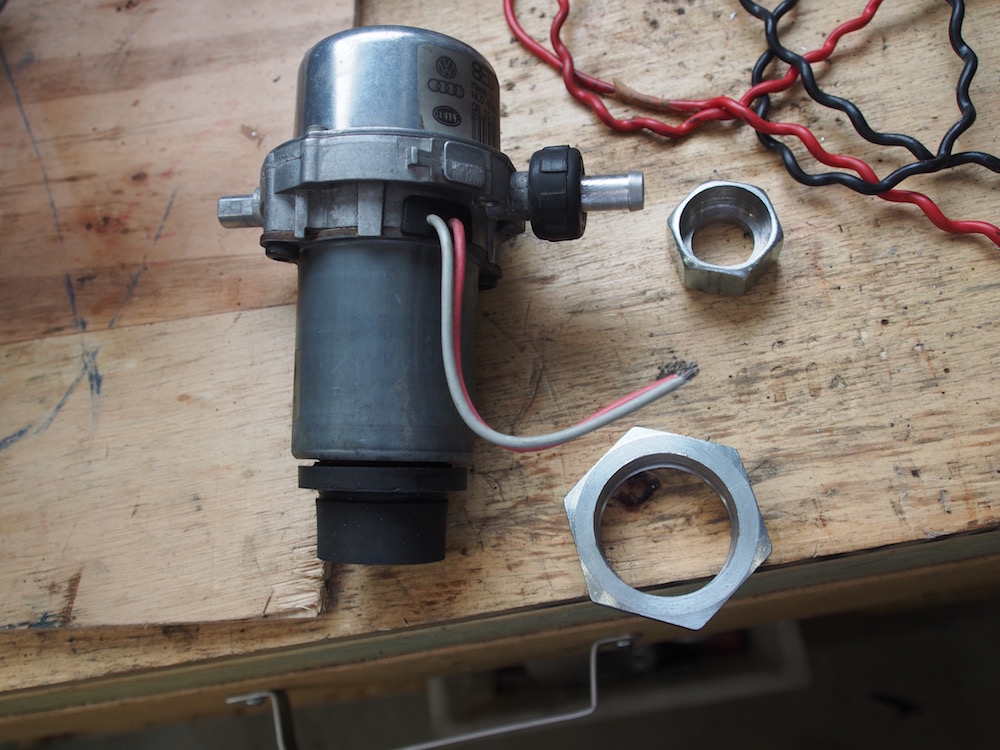
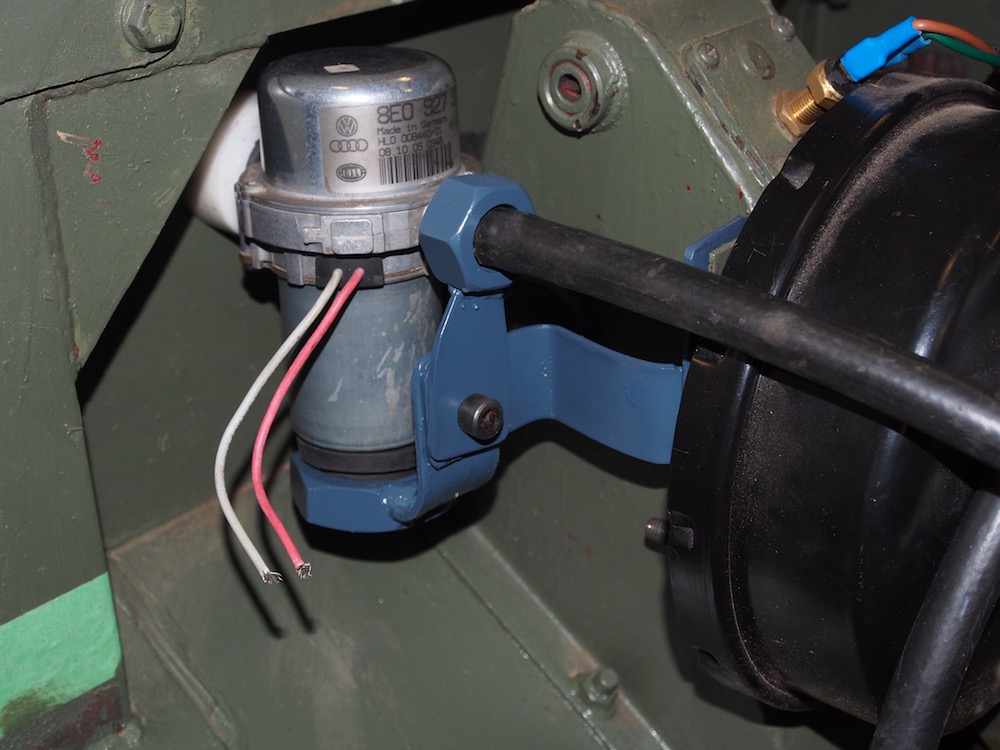
Browsing the DIY Electric Car Forums I found that many people are successfully using a 12v Hella brake Vacuum pump from Audi A4 & I was lucky enough to find one of those locally on eBay.
A vacuum switch must be plumbed in so that the pump shuts off when approx 17"Hg vacuum is attained, Otherwise the pump will run continuous & burn out, its not designed for 100% duty cycle. Luckily the Land Rover Series 3 brake servo has a bung with the correct 1/8" NPT thread to accept a Aeroflow AF49-2011 Vacuum switch. This is used on Land Rover diesel models to activate a Low Vacuum warning !!
I made a bracket to mount the pump with rubber isolation, using existing bolts, (be aware of bonnet clearance when closed)
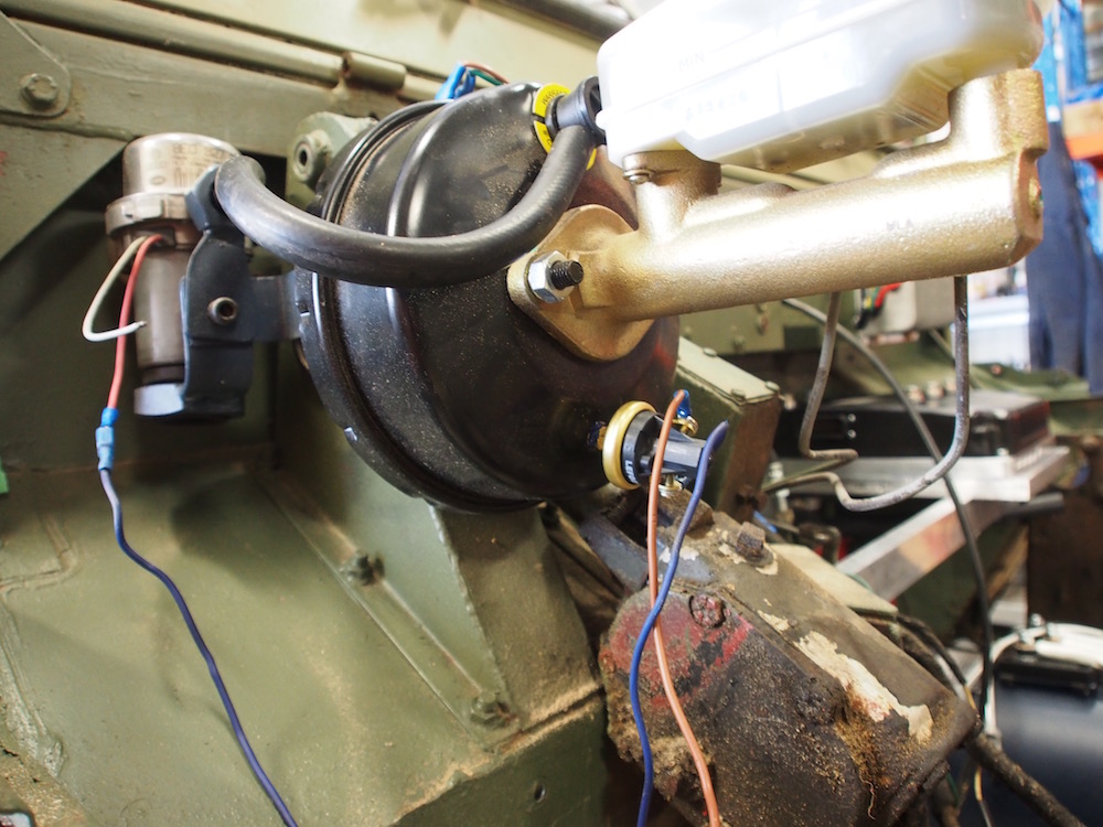
UPDATE 2024 : The Vacuum pump 'brrrrrp' noise finally drove me nuts & I converted to Disc brakes & a Tesla iBooster - more on that later
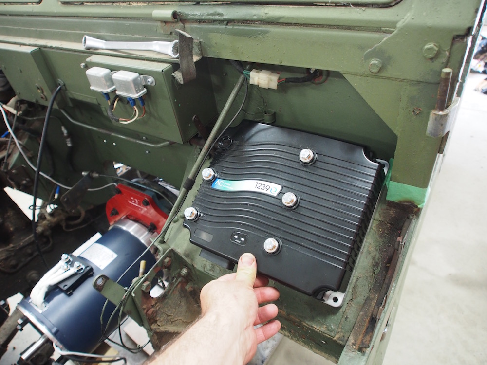
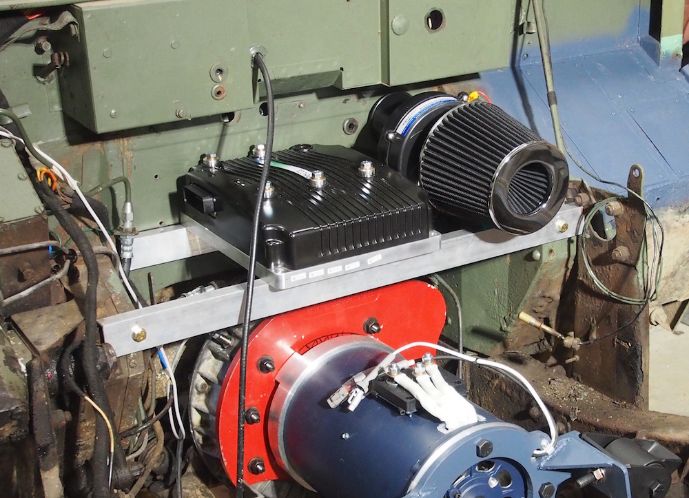
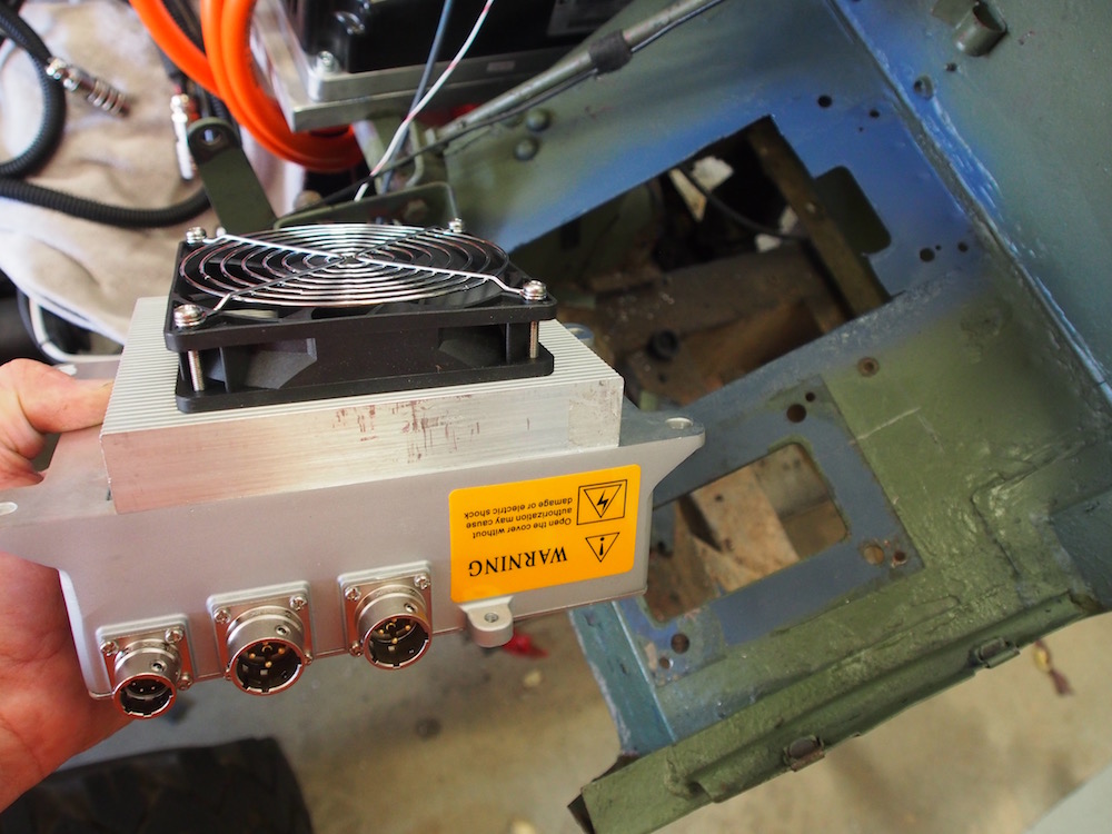
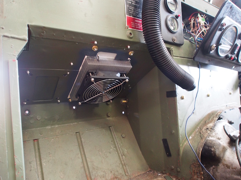
Motor Controller
The Controller is really a VFD ( Variable Frequency Drive ) which converts the 144V DC (500Amp ) to 3 Phase AC power. The Frequency of the AC power varies to adjust the speed of the motor according to the throttle position. Model designation is Curtis 1239E which is sold with the HPEVS AC51 as a combo, It also included enough wiring loom length to cater for a rear mount installation eg VW, the Spyglass & menu button, A Gigavac/Tyco 200 contactor, precharge resistor with electronic relay & a carling switch. I'm not sure what the switch is for as there are no instructions, not to worry it fell on the floor & the dog chewed it up !!
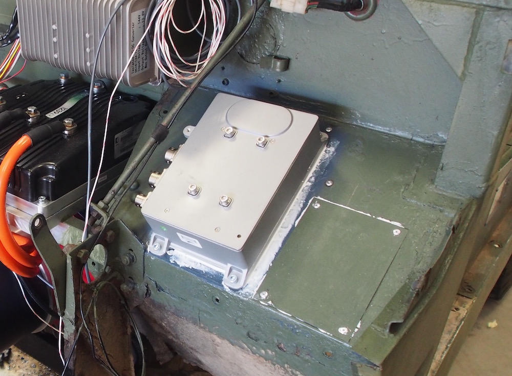
Decisions, decisions , where to mount the controller ??
I decided to fix some aluminium rails on the firewall using existing holes, this makes use of otherwise wasted space formally occupied by the rear of the old engine. I'll be able to mount the ducted cooling fan for the motor here too. I'll mount the charger (when it arrives from China) on the grey painted area above the passenger footwell.
Whilst looking at the HPEVS website for Ideas I notice they have a liquid cooled 'chill plate' for the Controller, Apparently they run quite hot if you push a lot of amps through them & can go into "cutback" mode, that sounds too much like Limp Mode, Im quite familiar with Limp Mode as I drive an Iveco 4x4.
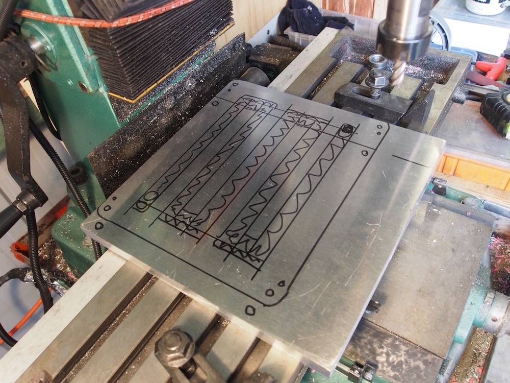
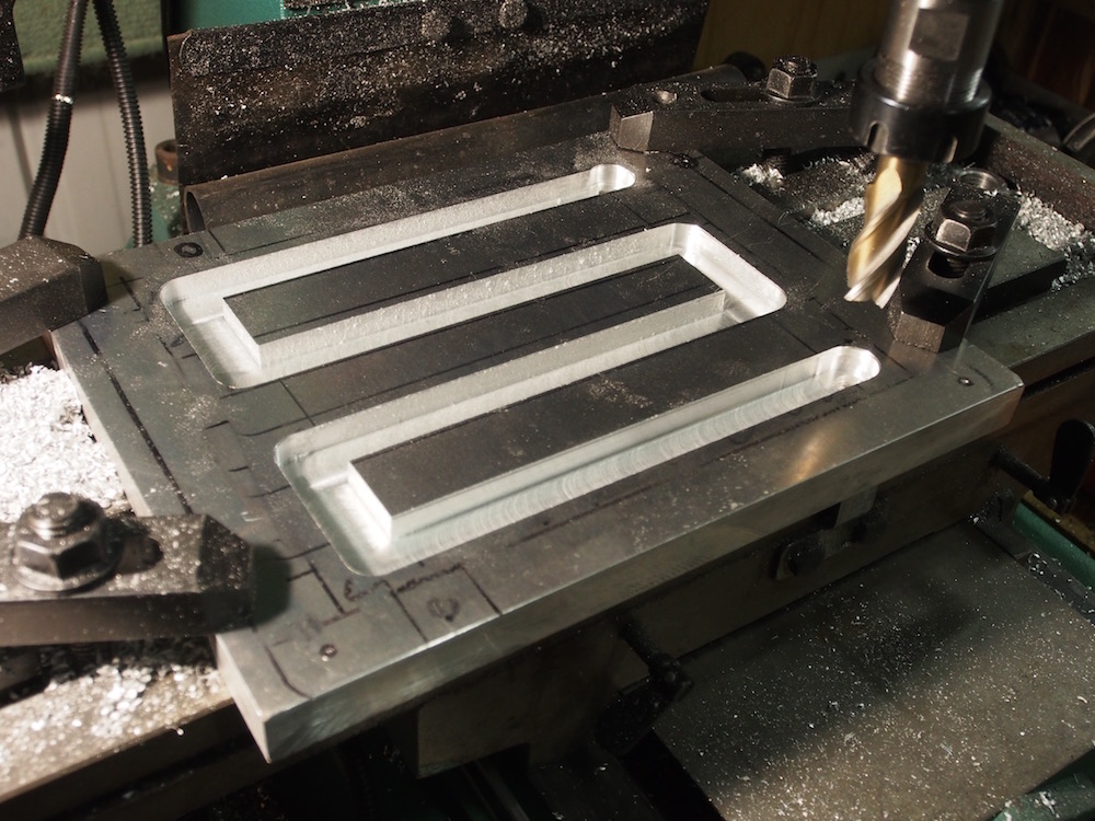
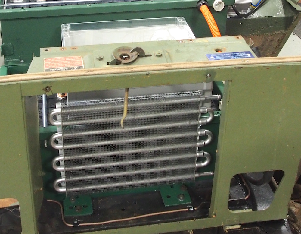
I had already planned to mount a big heat sink and fan under the controller but I like the chill plate idea better !!
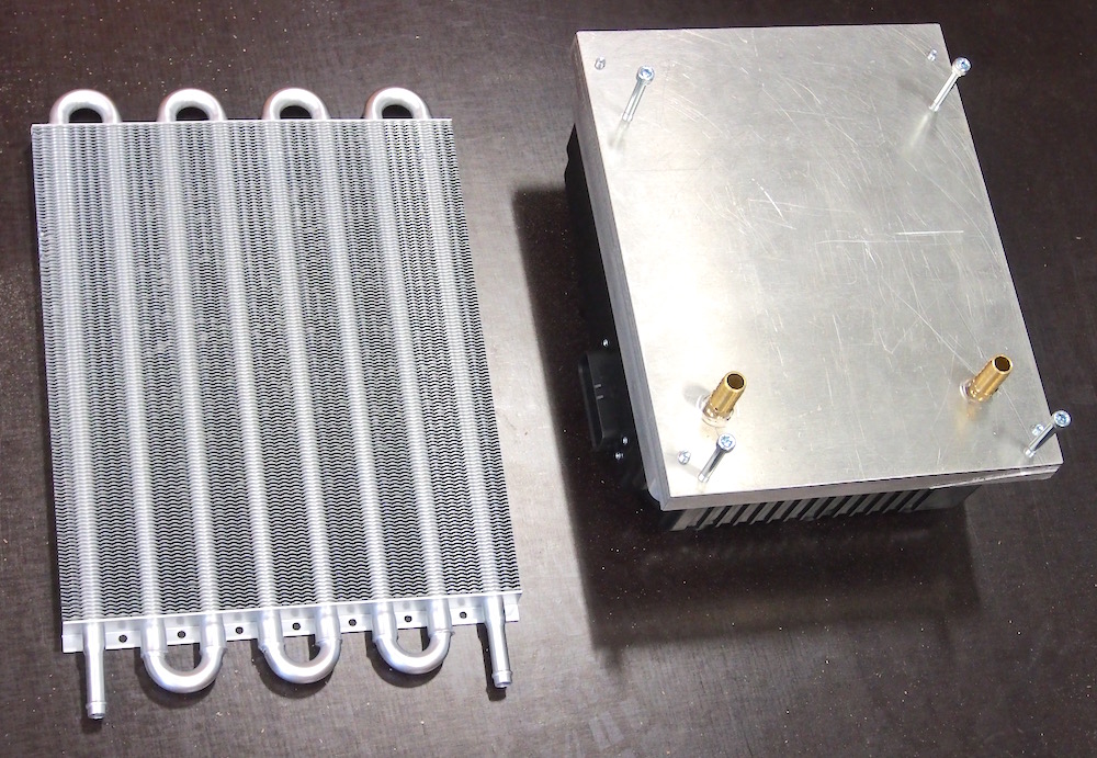
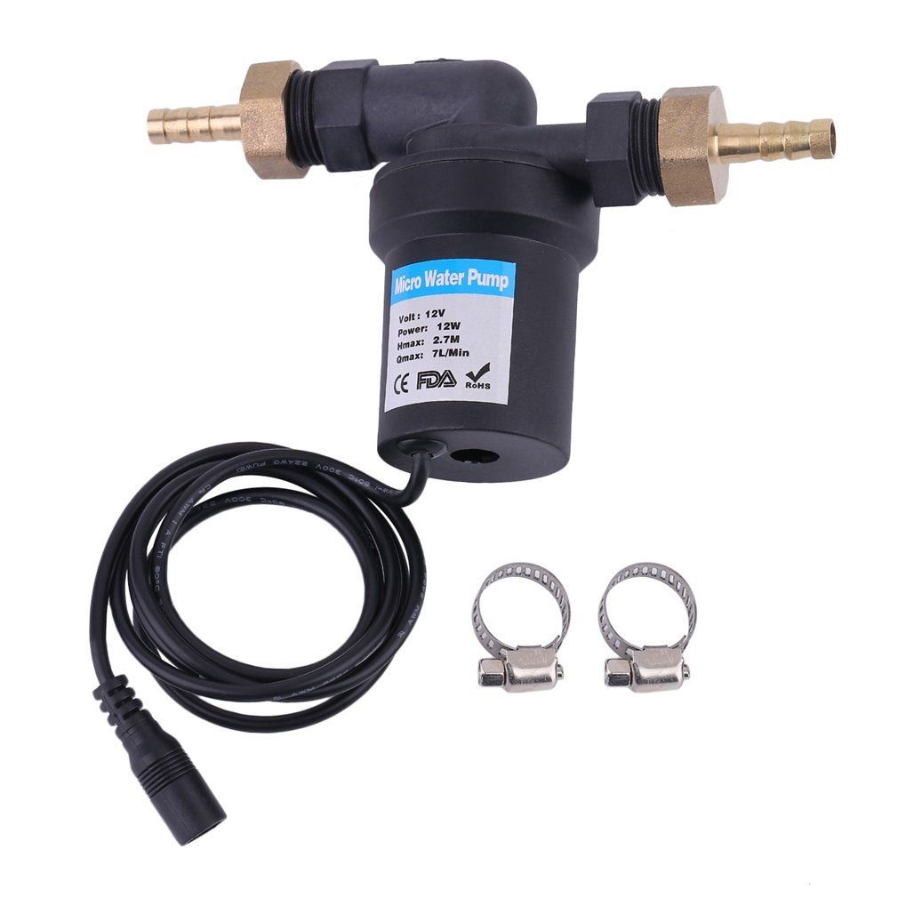
I had a 300x 300 x 20mm slab of alloy so got to work on the Milling Machine. After about an hour I had a chill plate better than a shop bought item (it was free) sealed to the bottom of controller with Hylomar sealant. I added a couple of 1/4"NPT bungs & plumbed into a transmission cooler mounted on the front battery box. Water / coolant is circulated by a small eBay 12V 12W solar pump, usually found in backyard water features.
I was going to use the original FFR Oil Cooler but it mounted the front battery box in the oil cooler holes. For the purpose the transmission cooler is more than adequate.
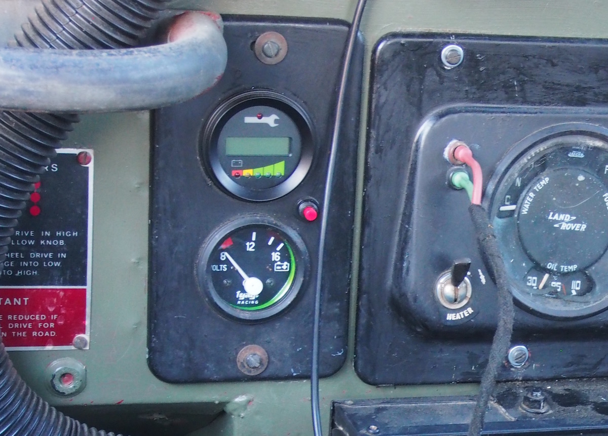
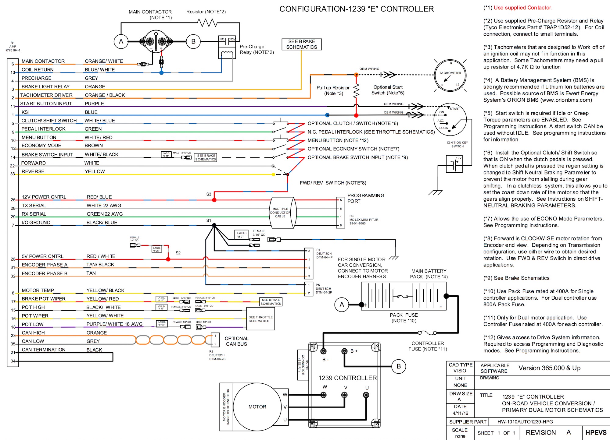
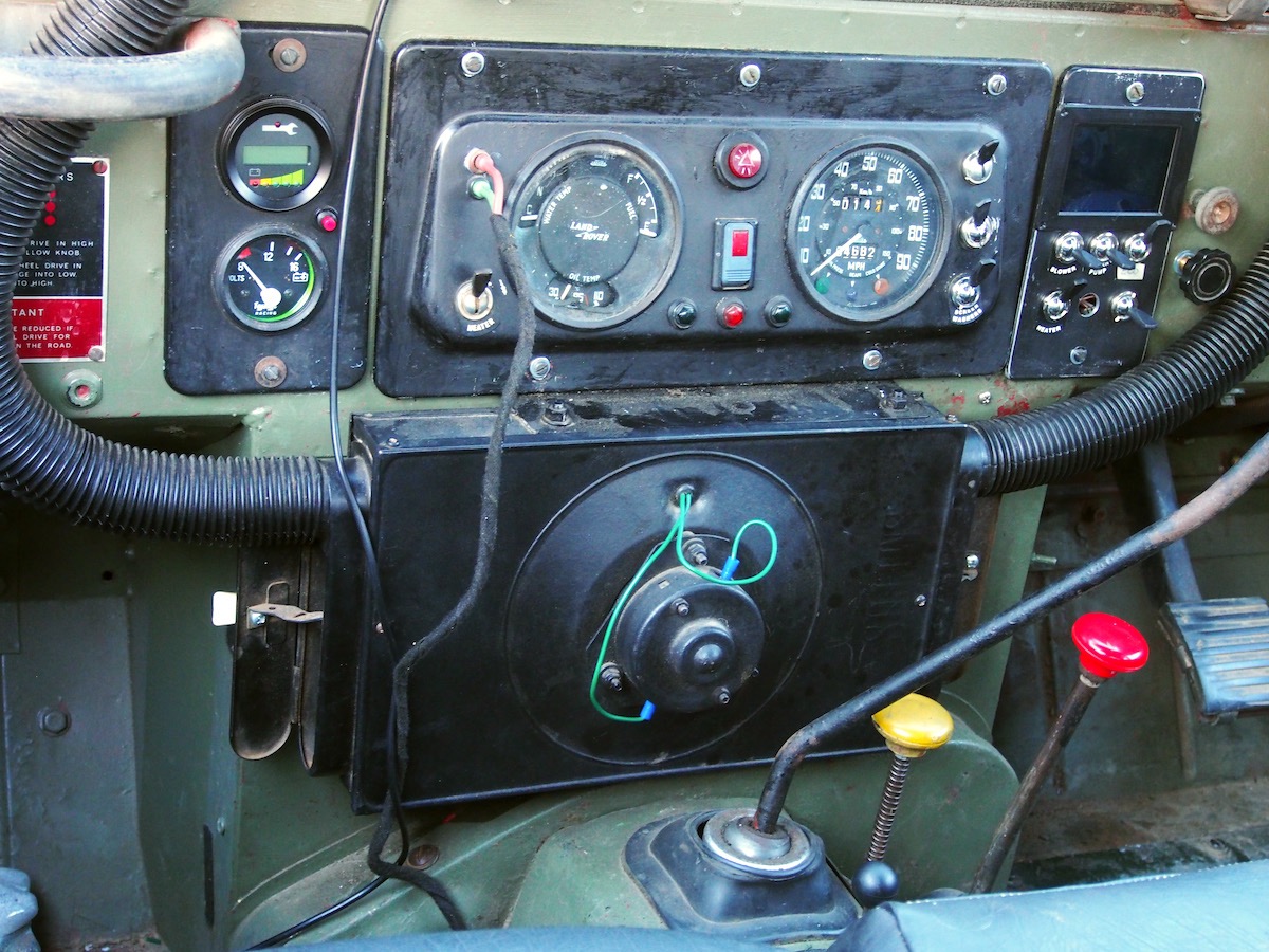
Here is the HPEVS wiring diagram for the 1239E controller, Everything is programmable through the Spyglass & menu button. Luckily the spyglass is housed in a traditional 2" gauge & I had a spare 2" hole which was once used as the 24V Ammeter when the vehicle was in Military service as a Radio Truck.
Throttle
Obviously, per the wiring diagram, we now need an electronic throttle, The Controller can be programmed to accept a number of different styles including 2 or 3 wire 5k pot and hall effect pedals, I did entertain the thought of using a Fly By Wire pedal from a Td5 Defender, as it would bolt right on, but just looks wrong in a Series Land Rover. The potentiometer I chose is a Curtis 2wire PB6 with microswitch as commonly used on golf carts. I liberated the throttle rod and ball joints from the old Zenith carby linkage which suit the purpose perfectly.
I installed another 5K wirewound pot on the firewall in the hole formerly occupied by the hand throttle. Can be adjusted by hand which I will use to control the amount of regen braking.
UPDATE: After about 4000km I started to notice a throttle glitch & needed to reprogram the throttle deadband to regain the driving feel I had become used to. I decided that a non contact Hall Effect type throttle would be more reliable than the wirewound & wiper Golf Cart style.
Browsing eBay I concluded a Honda CRV pedal would not look too much out of place. The electronic unit from the Honda pedal is fully sealed so is dust & waterproof. It is a dual sensor , one at 3v & one at 5v , The 5V circuit is compatible with the Curtis controller. Should last a lifetime. I made a Delrin plinth to mount the Honda throttle on, The plinth mounts to the bulkhead using 2 existing holes.
Once I adjusted the programming to suit a Hall Type throttle and reset the deadband, the vehicle drove better than it ever did with the golf buggy throttle. The look of the pedal sure suits the Series 3 more than a Defender Td5 or Puma throttle pedal would have.
Forward / Reverse switch
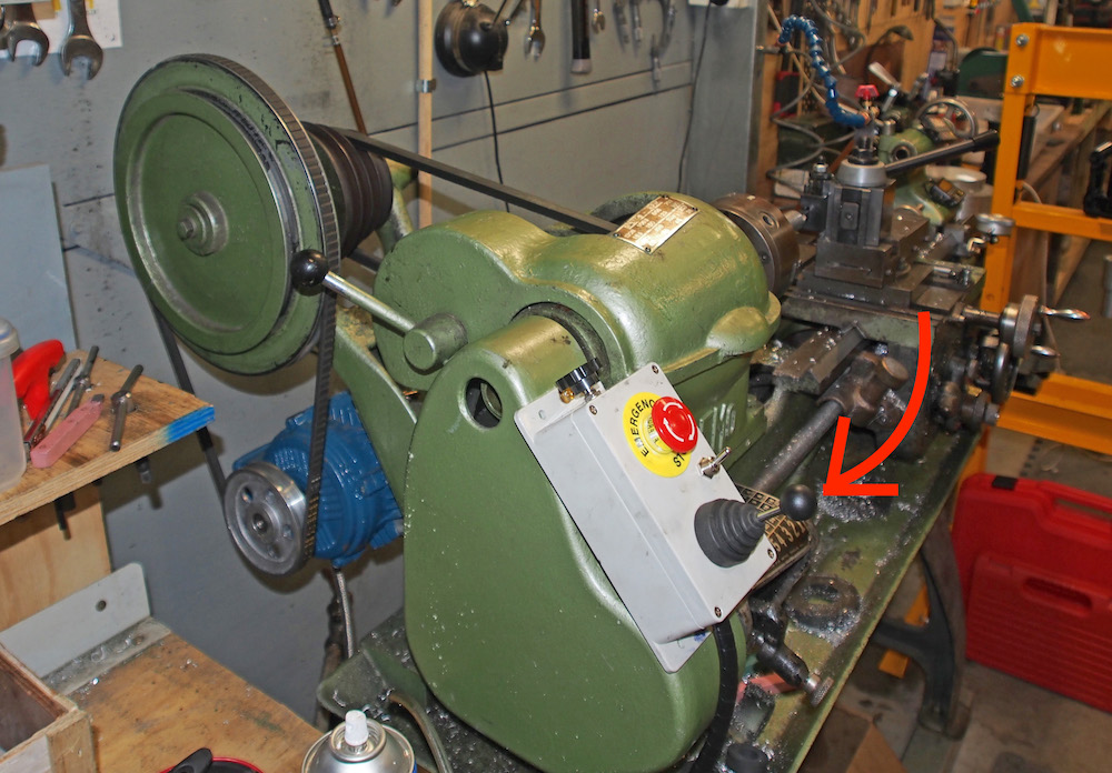
I'm not sure what most DIYers use for a forward reverse switch, Any DPDT toggle or rocker switch will work just fine electrically, but I wanted something classical looking that would not be out of place in a Land Rover. The exact thing is on my Lathe to control Forward / Reverse and considered one of those would be just right mounted on the big rubber bung on the gearbox hump.
It's a momentary switch which means the circuit only closes whilst you hold the lever forward or reverse so I made a veroboard circuit containing three PCB relays to latch the circuit when the lever is used, whilst I was at it I made it operate the reverse light. By default after the car is switched off and restarted the direction is always forward, and in compliance with NCOP14 a 2 action sequence is required to engage reverse (a safety feature) so as well as moving the lever back a small momentary push button is also pressed to latch the relays.
UPDATE; The lathe control switch soon failed (as has the one on the lathe) & I replaced with a COBO Forward Reverse lever from a Forklift.
HAZV wiring
Some explination, copied from National Code of Practice, document VSB14
Below excerpt also from from NCOP14
-----------------------------------------------------------------------------------------
"2.7 Marking of Hazardous Voltage Components
Electric vehicles usually employ higher voltages than normal internal combustion vehicles andconsideration needs to be shown to the safety of the end-user of the vehicle, service personnel,
and emergency responders in the event of an accident.
Consequently, all components in the vehicle containing a connection to a HAZV battery pack, or
which contain HAZV relative to the chassis, must be clearly labelled.
All wiring in the vehicle connected to a HAZV battery pack (either positive or negative),
or containing HAZV relative to the chassis of the vehicle, must be coloured orange even when
installed within orange conduit. A short length of red or black heat-shrink may be used at the
ends of the cables to indicate polarity as necessary. For all new wiring, orange coloured wiring
must only be used for HAZV circuits. (Original wiring harnesses fitted by the vehicle manufacturer
that contain orange wiring do not need to be modified to remove the orange wiring).
Red and black wiring colours must be reserved for ELV circuits."
------------------------------------------------------------------------------------------------
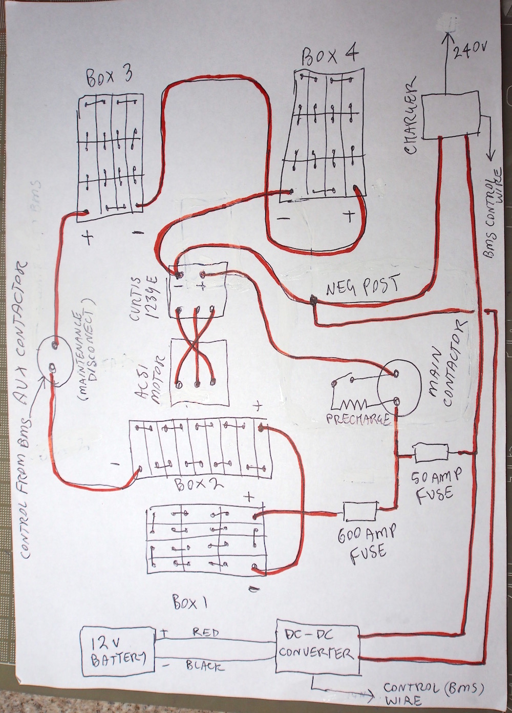
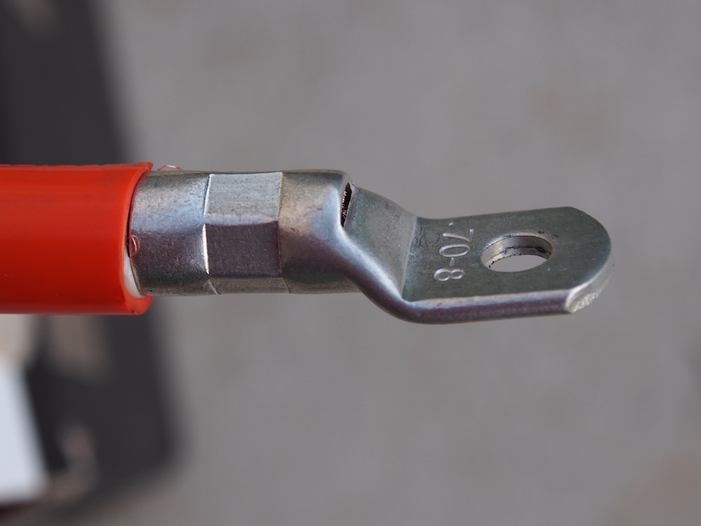
With the above in mind I designed my wiring layout and purchased 12 meters of 70mm2 Orange double insulated bossweld welding cable and a 25 meter roll of 25mm orange flexible conduit.
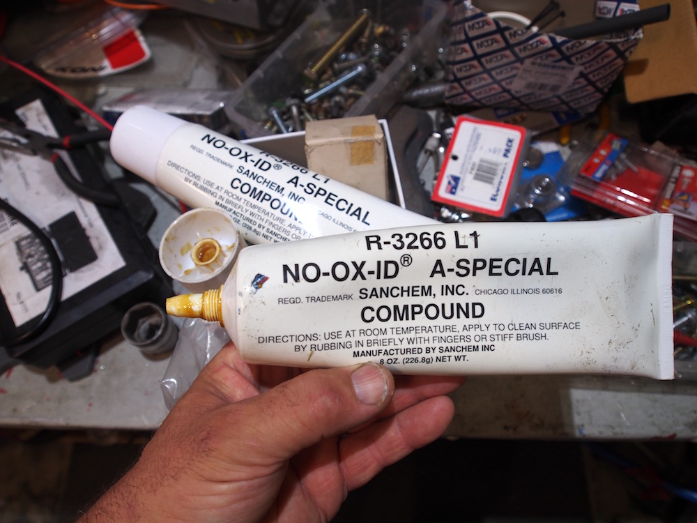
Other items needed for HAZV electrical hookup were a box of 70mm2 x 8mm (bolt hole) bellmouth crimps , a Hydraulic crimping tool ($35.00 from eBay, why didn't I buy one years ago) assorted P-Clips, cable ties, Adhesive lined heat shrink, Insulated cable lug boots, & very importantly a tube of Sanchem NO-OX-ID dialectric grease.
Having worked in telecommunications for 30 years I can not stress highly enough that you need to provide oxidisation control to all your cable crimps and battery connections. Especially when you are working with dissimilar metals & electricity . Sanchem NO-OX-ID is extensively used in Telecom battery installations, which are not dissimilar to EV battery installations, dont build an EV (or Powerwall) without a tube handy. One Tube is plenty for a typical EV. The LiFePo4 Cells have an Aluminium positive post, a Copper negative post and we are using stainless bolts & copper busbars / cable lugs. Apart from dissimilar metals Stainless & Aluminium have a tendency to gall & the grease prevents this. Don't forget to clean the oxidisation from the lugs and connectors before adding the grease, 200grit abrasive or a stainless wire brush)
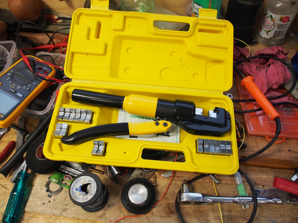

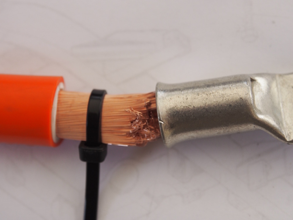
The picture above shows a straight crimp but flared bellmouth crimps are easier to install as the fine strands of the orange welding cable are easier to insert prior to crimping, even then a small cable tie around the strands helps with insertion. ( Cut the cable tie & remove it before pushing the lug home )
(Prepare the lug by giving the inside a rub with fine abrasive paper / wire brush to remove oxidisation & a light smear of grease)
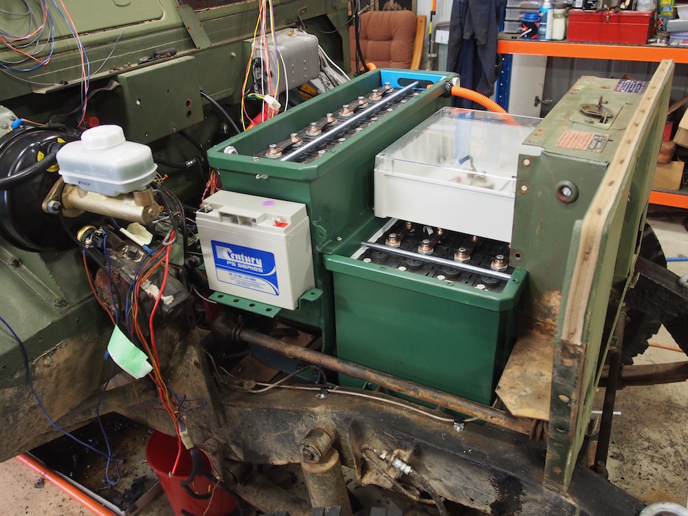
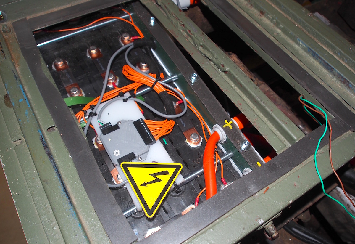
I ran all my exposed HAZV wiring inside 25mm conduit & fixed with P Clamps according to Electrical regulations, using glands as necessary to enter boxes. All my HAZV switch gear & fuses inside an enclosure with clear lid mounted on top of the checker-plate lid of the front battery box. This helps protect from moisture and centralised for easy access. The main fuse still as close to Battery positive according to NCOP14.
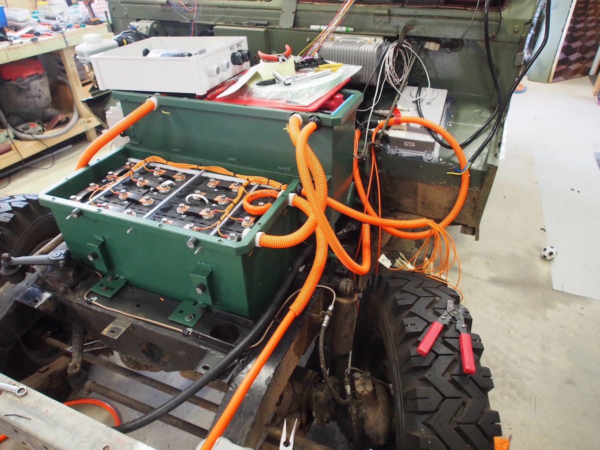
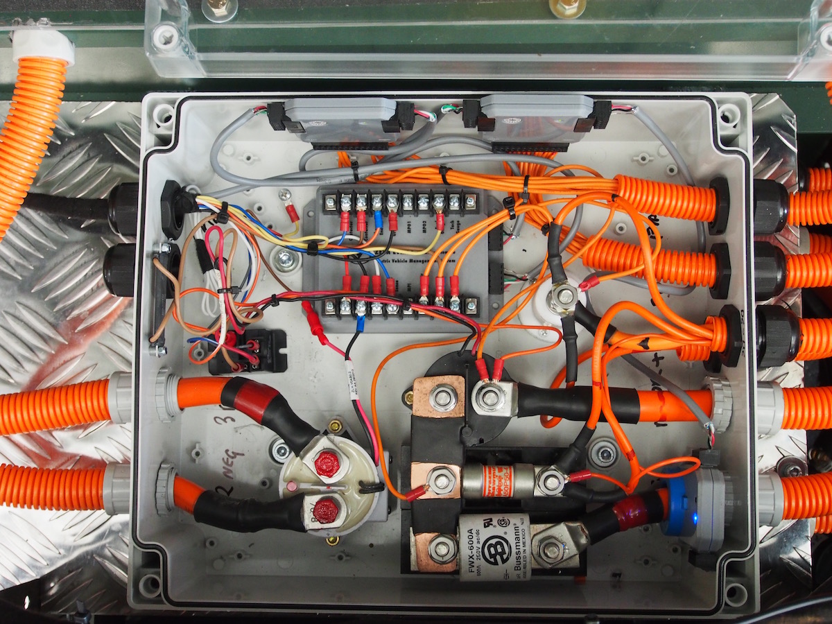
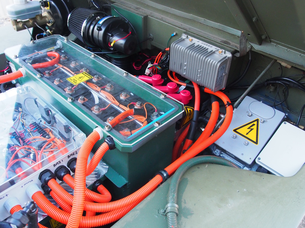
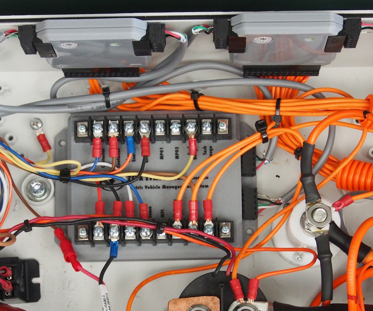
The Grey parts in the enclosure are components of the Zeva Battery monitoring system (BMS) also use orange wiring but is very low voltage as it is sampling the cell voltages only, but still is classified as HZAV because it is connected to the Traction pack.
Zeva BMS
I did toss up my BMS options & even thought about going without one, one school of thought is that manual bottom balancing alone is all you need. The battery packs can still be monitored by use of a voltage divider circuit & LED indicator, eg " Battbridge" but due to the fact that my two under-seat Battery boxes are relatively difficult to access I thought it better to be able to easily monitor individual cell voltages. I chose to use the Australian designed and made Zeva BMS. I am one of the lucky first to get the new Version 3 BMS.
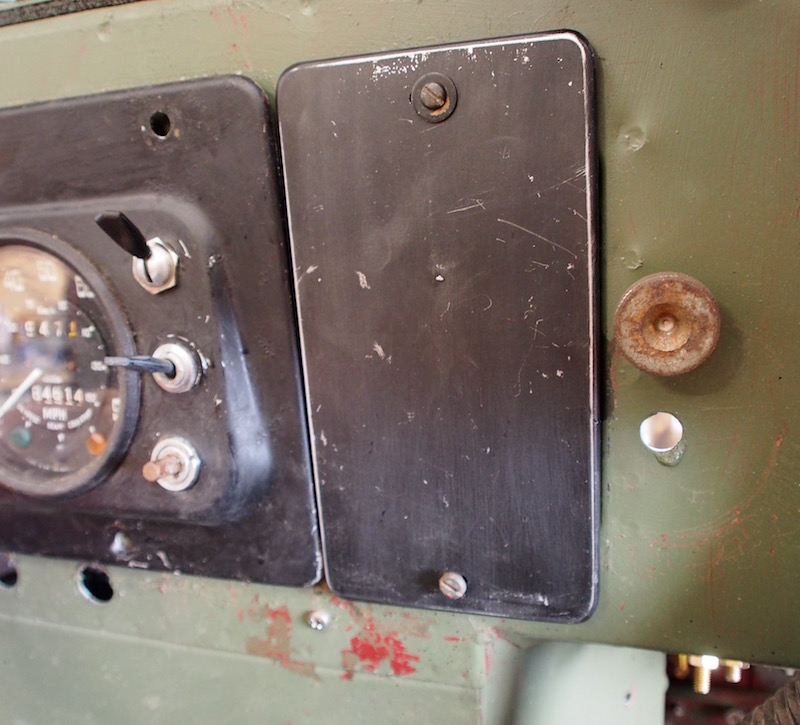
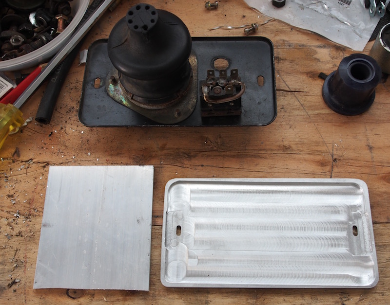
The main reservation I had with the BMS is the TFT monitor, There seemed to be no obvious place to mount a modern TFT display so opted for the Panel mount display rather than dash-mount enclosure (obviously there is no dashtop in a Lightweight) It was not until the "Panel Mount" TFT screen arrived that I realised it would fit on the right side auxiliary panel which mounts the military light switch & wiper / washer knob. Rather than botch up a rare Lightweight item I made a new panel from 6mm Alloy plate including "new patina".
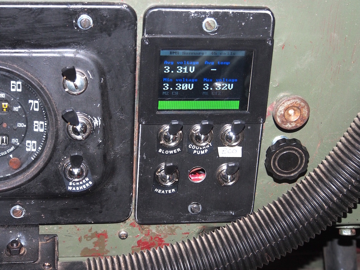
Externally the only clue to any modern technology is the TFT display, but when its off no one would think anything odd about it, so I'm happy with the result even though the TFT bezel is slightly wider than the alloy plate. The traditional Land Rover Lucas switches on the panel are "Blower" this supplies clean air to the motor inlet. "Coolant Pump" powers the 12V solar water pump to cool the controller. "Eco" (I'm waiting for the bespoke tag from UK) activates economy mode, extends range, decreases performance. "Heater" switches on the ceramic heater elements inside the original Smiths housing, empty position for Flux Capacitor, Last switch is "Regen", to disable regenerative braking ( waiting for tag), Bakelite knob (from old Valve Radio ) on firewall in former hand throttle position is regen adjust, or adjustable "hill descent".
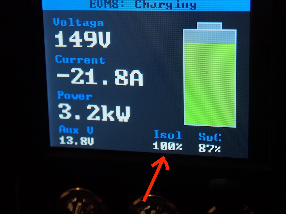
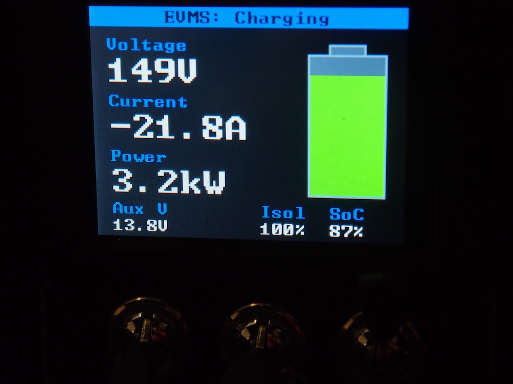
One feature that I'm also very happy about is the Isolation readout . NCOP14 regulation stipulates the HZAV circuit is isolated from the chassis by a leakage current of less than 20mA, I suggest that is a reasonable figuire ( 240volt RCD trip current is 30mA). My BMS indicates I have 100% isolation & no leakage. Without this feature on the BMS I would have no idea . !!
Above is the BMS display during the first charging, The cells are all happily balancing at 3.40 then shortly after one cell goes high and the BMS aborts the charging so as to not overcharge one cell. I discovered with a bit of research and some help from DIY electric car forum that LFP cells actually don't like going too far above 3.4 ( China says 3.6) I will back off the BMS paramaters to stop charge at 3.45, especially in this hot Summer with daily temps around 42c
The little green bars represent individual cells, orange bars indicate the cell is being shunted so as to keep cells in balance.
Here is a link to a great dissertation on Lithium Batteries
UPDATE: Battery Status after 6 years
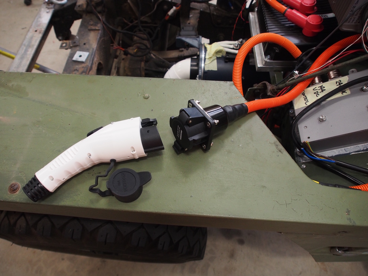
The batteries show no signs of degradation, as expected they do perform better in Summer than Winter, Lithiums take on less charge at temperatures below 15°c . In the last few months I've added a HV outlet (in image at right) so that I can draw power from the batteries to feed into the house at peak times or back to the grid, This had done wonders for the battery health as allows regular bottom balancing. Normal driving does not bottom balance the cells. They only get a top balance when you charge.
DC-DC Converter
Just like with an Internal Combustion Engine (ICE), Electric Vehicles also require a 12V wiring system and battery for mandatory safety equipment, lights , wipers, horn ect and importantly in the case of an EV so that the High Voltage contactors can be energised. NCOP14 also mandates that the Hazard lights must be able to operate for 20 minutes when vehicle is otherwise disabled.

The DC-DC Converter takes the place of an Alternator & in our case converts 144V to 12V (13.8V) to operate the 12V equipment and keep the 12V battery charged. Of course technically you could delete the battery and have the DC-DC Converter in HZAV circuit all the time but you would require a Manual Maintenance isolation switch instead of an Electronic Contactor, and some DIY EV's do use this method.
I chose to use a small Sealed Lead Acid, 18Ah Deep Cycle battery, (Century PS12180 ) interestingly this battery is less than half the physical size of one SinoPoly 200Ah LFP cell but noticebly heavier !!
Because of the small 12v Battery capacity and NCOP14 requirement for 20 min Hazards I changed my 4 x 18W incandescant indicator bulbs for Low wattage LED bulbs and an electronic flash can, Hazards easily go about an hour.
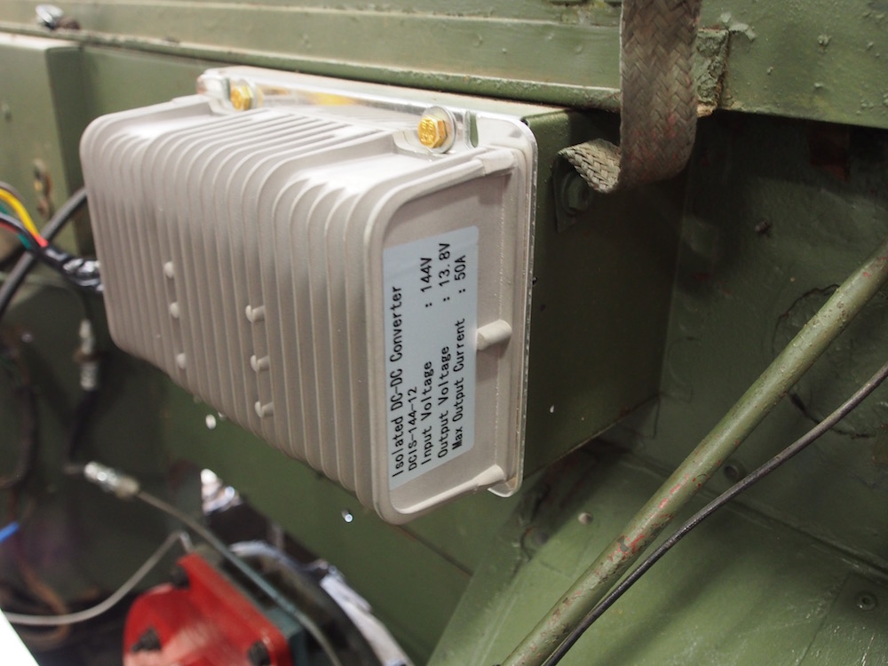
Since I am converting a 4x4 I need equipment that is fully sealed against water & dust. It took a bit of searching but I found a converter on AlExpress that none of the EV Vendors have listed, Its fully sealed IP65, isolated (well below 20mA ) and direct from manufacturer is amazing value.(around $100) Only 50Amps but that's fine as my old Alternator was only 35Amps. It took about 6 weeks to arrive but so impressed that I bought another (just in case I needed more current as you can piggy back them.)
Also, importantly this DC-DC converter is dimensionally perfect & fits exactly onto a sheet-metal protrusion on the Land Rover Lightweight firewall.
Heater
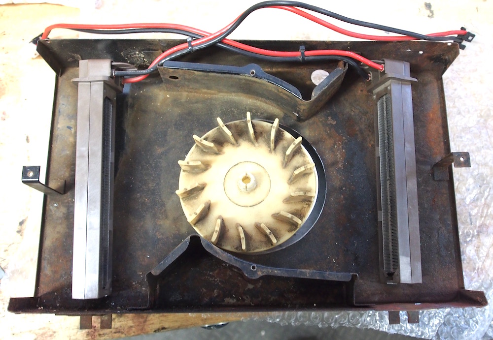
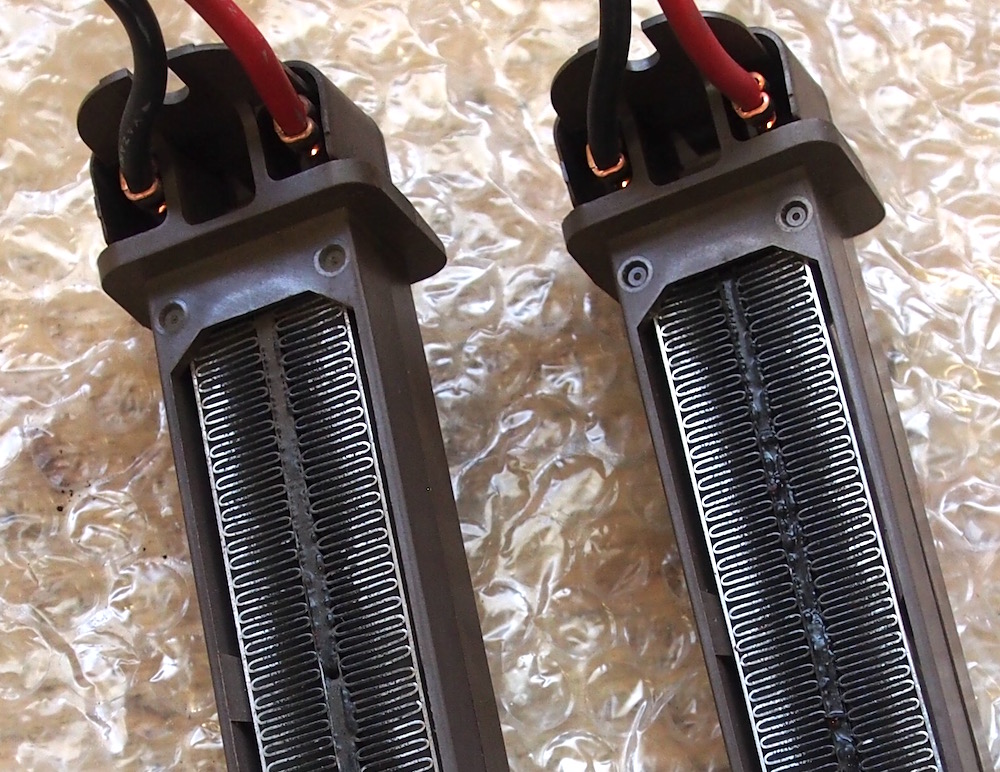
I installed 2 x 12Volt Ceramic heater elements inside the Smiths housing inplace of the water element. Connecting it to my old ZZ70 battery it worked brilliantly, too good actually - the fan must be running or else the elements overheat.
The problems came when I tested the heater for the first time in the vehicle. I had both elements wired in Parellel connected via a pair of 30Amp relays and a 30Amp circuit breaker.
The current required by the Heater overwhelmed my small 18Ah battery and caused the DC-DC Converter to stall and circuit breaker to trip, the solution was to wire the elements in series, no problems now , I have it wired so the heater fan must be running before heater elements will turn on.
Despite every day being above 38c since I have completed the project I can easily feel warmth being blown from demister ducts so it will be plenty of heat during winter & satisfy ADR requirements.
Unlike a Petrol car, the heat is almost instant, no need to have engine running 10-15 min before windscreen clears!
Charger
I chose to install an onboard charger, to give me the versatility to charge at any 240V power point. For the same reason as the IP65 DC-DC charger I wanted a fully sealed charger, they are not in abundance. A bit of internet research led me to the TC HK-J Series 3.3KW Fully Sealed OBC. Being 3.3Kw it needs a 240V 15Amp supply, luckily I already had a 15 Amp circuit installed in my shed, but I might have difficulty finding 15Amp points out and about ( except for Caravan Parks, they are all 15Amp outlets .... I could tour from Caravan Park to Caravan Park ) These chargers are custom made in China to suit your battery pack so as to not overcharge ( Mine cuts off at 165V ) you also have the option of CANbus control or manual control, I ordered manual because at the time I did not know I was getting a Zeva BMS (which can talk to TC charger) No problems the Zeva controls a relay which switches the charger off if required. Took about 8 weeks delivery.
The charger fits conveniently on the passenger side footwell, I removed the riveted plate that covers the hole for LHD brake pedal fitment and with a little trimming was able to neatly flush mount the charger with heatsink and fan into the passenger side.
The only problem with the charger is it has Chinese documentation and unusual cable termination plugs, hopefully I wont need any spares.
As can be seen on the Zeva BMS display the charger works as advertised, pumping out 21.8 Amps at 3.2kw .
J1772 Charge Point.
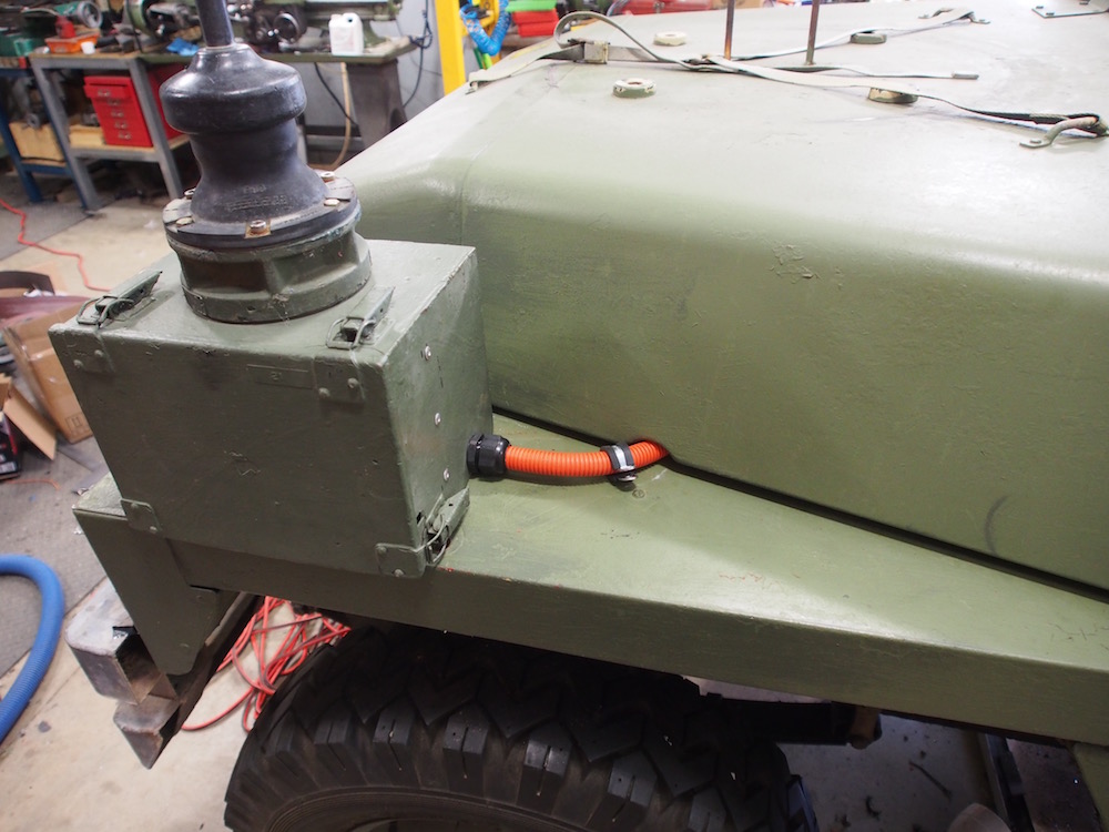
The last piece of the Lightweight EV puzzle, where to mount the charge receptacle? As discussed earlier there is no external petrol filler because of the underseat fuel tank caps. Because of the rarity of the vehicle I am reluctant to cut holes in the bodywork or grille. I had thought of buying a spare grille from UK but would not want to cut a hole in that either. Locations suggested were behind front bumper, in the rear guard tool box, in the rear cross member inplace of the trailer socket, and in the front wing mounted Antenna box !!
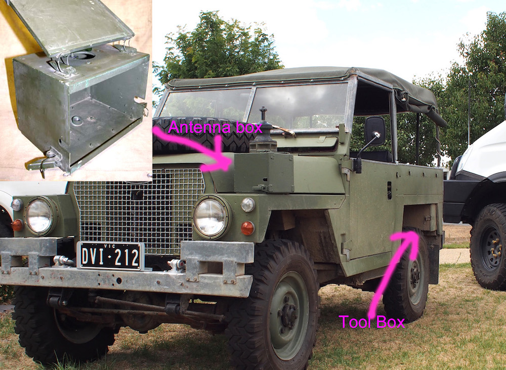
I decided the Wing box option was the most conveniant, I modified the box to accept the J1772 socket and drilled a hole for a cable gland, since this is 240V A/C Mains cabling & will never be 'live' whilst vehicle is in operation it does not need to be in orange conduit, will be painted green to look like Military antenna wiring. No holes needed to be drilled in the vehicle itself !!
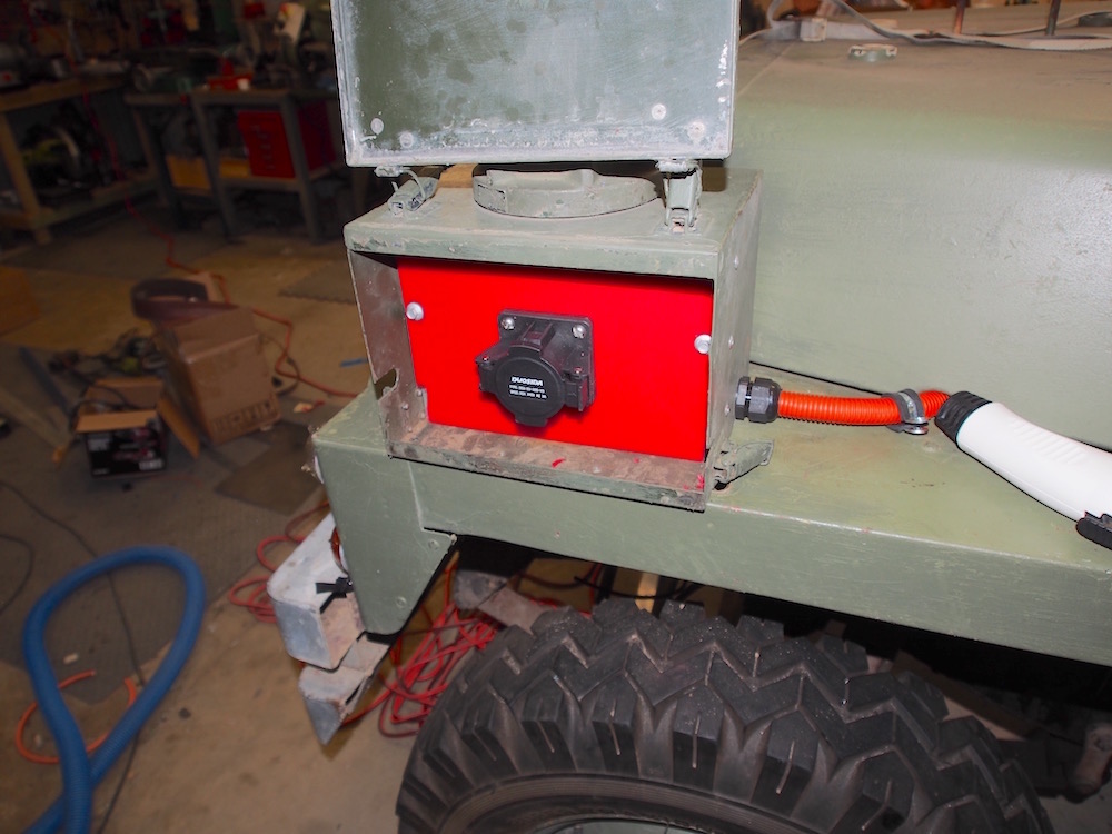
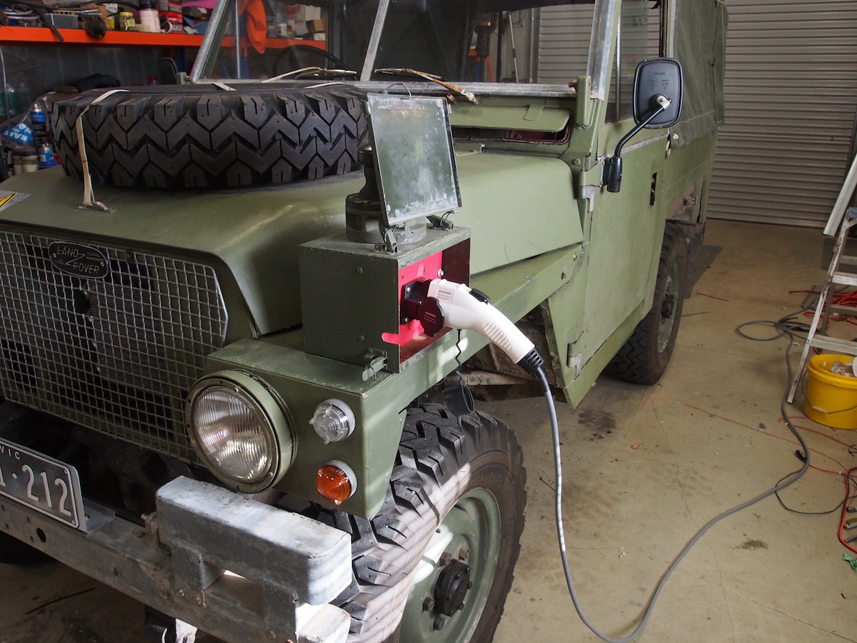
UPDATE: In retrospect it turns out I should have originally mounted in the rear tool box as a few years later I did indeed relocate the charge port to the rear tool box door and removed the FFR wing box entirely. .
Project Completion
Overall, What a bloody little ripper, after 4 months build, took it for a first test drive, and I got to say I was impressed. Its all I had hoped and more.
Glad I kept the gearbox though, Taking off in 4th is a bit sluggish . Using both 2nd and 4th its just great. Got up to 118kmh on the flat, Best I ever got before with Internal Combustion Engine was 98kmh flat knacker. Taking aerodynamics of a brick into account Sitting about 90kmh is comfortable, before 80kmh was about as fast as you wanted to go.
After a week of test driving it been too hot to do any meaningful range testing but after a 55km run of mixed conditions, some highway, some dirt & some around town I have 49% charge left. Extrapolating that I expect 100km is not going to be difficult, and more in the cooler weather.
Ive found that 3rd gear is a good compromise the Landy is happy chugging (whirring) off from a standstill & if anything is probably a little fast around town. I had to put a bigget spring on the throttle in an attempt to keep the speed down, there is a surging feel in the throttle, it only takes minute movement to go from a crawl (in traffic) to too fast. Flicking into "ECO Mode" helps, the throttle needs some fine tuning (through spyglass)
Problems
There were 2 problems with my Motor and its impossible to get after sales service from the vendor, EV Works in WA, they don't answer or reply emails and rarely take phone calls. I had to resort to using their contact form on webpage, still no help. Be prepared to phone HPEVS direct in USA if you want help. The motor temperature in my spyglass reads "Mtemp 496c" & I'm unable to get any help with this. DIY Electric Car Forums is a great resource & most any help you need is there but when you spend multiple thousands you expect the first instance would be from the Vendor.
In the meantime I'm adding a Thermocouple to my Zeva BMS & will read motor temperature from that.
The other problem with my motor is if wired up according to instructions it will NOT run, DIY Electric Car Forums to the rescue & I transposed my Phase cables " U & W " to solve the problem.
Conclusion
This is the worlds first Land Rover Lightweight EV conversion and one of only a handful of Series Land Rovers to have been converted (at time of writing in 2018). I know some Purists are not happy with what this, it's my car, not theirs, but I have kept all the old parts and can easily revert to original. Would I ever do that ?? NEVER, this Land Rover is soooo much better to drive than with internal combustion. And for the first time ever I can drive a soft top Land Rover without being overcome with petrol, oil & exhaust fumes, I know thats a Land Rover thing, but its a huge deal. Do I miss the tappety, chugging engine sound, Sure I do, but I can live without it.
I know there are EV Haters out there, to those I say, drive an EV just once before making uninformed opinions on the basis of social media diatribe. The arguments about range , that Australians need to be able to drive long distances, Valid yes, but at least 90% of car trips are short commutes or to the shops. And then the arguments about EV's still use non renewable energy in the form of Coal burned at Electricity generators, fair enough, I'm no greenie, not by a long stretch, but I generate more Electricity with our 10Kw solar array that I'll ever use charging the Land Rover.
In all a bloody good project & glad I did it, Externally the vehicle is identical, except for lack of a exhaust tailpipe.
Here is a link to a great dissertation on Lithium Batteries
Before & After
Here is a before & after comparison on the same stretch of road.
Petrol Engine vs Electric motor
Yes, its still noisy, Its a Land Rover , still has gear noise, tyre noise, wind noise, but form the outside its super quiet
Press
The EV Landy has created some interest out there.

Unsealed 4x4, 12/11/2018
 LRO Magazine June 2018
Some interesting EV Land Rover links
EV Land Rover Series 3 in GermanyLand Rover's own EV Hybrid Series 3
Facebook Group : Electric Land Rover and 4x4 EV Conversions
Australian EV Association
Milbay Australia
Zeva BMS
DIY Electric Car Forum